Series I L27 (1992-1994 SE,SLE, SSE) & Series II L36 (1995-1999 SE, SSE, SLE) and common problems for the Series I and II L67 (all supercharged models 92-99) Including Olds 88's, Olds LSS's, Olds 98 91-96, Buick Lesabres and Park Avenue 91-96. Please use General Chat for non-mechanical issues, and Performance and Brainstorming for improvements.
here is a quick diagram. The DPDT (center off) switch is shown in center position. Throwing the switch "up" connects the yellow wire to ground, which turns on the pump. After the struts are fully extended, moving the switch to the center/off position removes the ground from the yellow wire stopping the pump. This is called the "hold" postion. Throwing the switch "down" connects the white wire, which is the purge line. This would be called "normal" position as the purge and inflate functions are intact.
Okay, so I've finally got around to buying the $3.00 switch, however, I have two questions...
a) I bought a SPDT (versus the DPDT) switch. Any difference? On the switch is says 12V20A.
b) from the diagram above I'm confused because there are only 3 terminals on the switch. Should the white wires go to the middle and bottom post, the yellow to the top AND a ground to the middle? Please clarify. Thanks.
Yes, there are only two positions. The DPDT switch will have 4 terminals, and the SPDT won't work, as you will either be in inflate or normal, no purge. Return the switch if you can and get a DPDT.
Bye Bye: RIP sandrock
Sirius wrote:Think about it. You’re tooling down the road in your Prius, knowing full-well that this thing being green is as big a sham as federally mandated ethanol-enriched gas, Russia pulling out of Ukraine, and Obamacare.
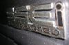
These are the best pictures I could take. (need a new camera). The numbers are fuzzy, but on the back side you can see the 1 and 4 are under the top two terminals.
No documentation. It was in a clear bag with cardboard hanger tag that reads:
DPDT Center-Off
Auto-Flip Switch
Contacts rated 20A at 12VDC
Again, using my picture posted, on the back of the switch there are corresponding #'s:
1 4
2 5
3 6
Using the wiring diagram given by sonoma_zr2, how would I connect this to the DPDT switch?
Is the first dot #1, second dot #2? Or is there a certain way to connect this? I don't want to go through the whole "just keep switching wires until it works" route.