Discuss your 2000-2005 Bonneville SE, SLE, SSEi, Buick Le Sabre 00-05 and Buick Park Avenue 97-05. Please use General Chat for non-mechanical issues, and Performance and Brainstorming for improvements.
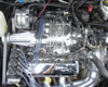
Secondary AIR Injection Pump Replacement
Secondary AIR Injection Combination Valve/Pipe Replacement
Secondary AIR Injection Vacuum Solenoid Replacement
DTC P0412 Secondary Air Injection (AIR) Solenoid Control Circuit
DTC P0410 Secondary Air Injection (AIR) System
DTC P0418 Secondary Air Injection (AIR) Pump Relay Control Circuit
The control module activates the Secondary Air Injection System by grounding both the pump relay and the vacuum control solenoid control circuits simultaneously. This energizes the pump and the vacuum control solenoid. Vacuum is then applied, opening the valves. The pump then forces fresh air into the exhaust stream in order to accelerate catalyst operation. The control module will run up to 3 diagnostic tests using the pre-catalyst HO2S voltage and Short Term FT to diagnose the system. The system can be diagnosed during normal Secondary Air Injection operation or the control module can activate the system specifically for diagnostic purposes. If an air flow problem is detected this DTC will set. When inactive, the system prevents air flow in either direction.
Andrew - owner/operator of Bonnevilles Unlimited 2004 Bonneville GXP | 60k | White Gold Tricoat | custom built supercharged 3800 hot rod | garage queen 1997 Corvette | 57k | Silver Metallic | Z06 wheels | Date-night Hauler/Parts runner 2014 Town & Country Limited | Cashmere Pearl | 115k | Family Hauler 2002 Ram 1500 Quad Cab Sport | Black| 280k | Official Bonneville Hauler
Yes, it probably will. You would have a mess of wiring and tubing to get rid of also. Its not harming you at all, just producing cleaner emissions. Just tell people its your special turbo
Andrew - owner/operator of Bonnevilles Unlimited 2004 Bonneville GXP | 60k | White Gold Tricoat | custom built supercharged 3800 hot rod | garage queen 1997 Corvette | 57k | Silver Metallic | Z06 wheels | Date-night Hauler/Parts runner 2014 Town & Country Limited | Cashmere Pearl | 115k | Family Hauler 2002 Ram 1500 Quad Cab Sport | Black| 280k | Official Bonneville Hauler
Its controlled by the PCM, but a Tech2 can do it also.
DTC P0410 Secondary Air Injection (AIR) System
Refer to Engine Controls Schematics Air Pump Motor and Vacuum Valve Solenoid, NC8 Only .
Description
The control module activates the Secondary Air Injection System by grounding both the pump relay and the vacuum control solenoid control circuits simultaneously. This energizes the pump and the vacuum control solenoid. Vacuum is then applied, opening the valves. The pump then forces fresh air into the exhaust stream in order to accelerate catalyst operation. The control module will run up to 3 diagnostic tests using the pre-catalyst HO2S voltage and Short Term FT to diagnose the system. The system can be diagnosed during normal Secondary Air Injection operation or the control module can activate the system specifically for diagnostic purposes. If an air flow problem is detected this DTC will set. When inactive, the system prevents air flow in either direction.
Conditions for Running the DTC
No EVAP, ECT, Fuel Trim, Idle Control, HO2S, MAF, IAT, TP or Misfire DTCs set.
The engine run time is more than 90 seconds.
The fuel control is in closed loop.
The engine coolant temperature is between 65°C and 110°C (149°F - 230°F).
The mass air flow (MAF) is less than 8.1 g/s.
The ignition voltage is more than 11 volts.
The engine speed is more than 850 RPM.
The fuel system is operating in DECEL control cell.
Conditions for Setting the DTC
The pre-catalyst HO2S voltage remains above a predetermined lean value during the test. AND
The Short Term FT does not increase a calibrated amount during the test.
Both conditions above exist for 3 consecutive tests.
Action Taken When the DTC Sets
The PCM will illuminate the malfunction indicator lamp (MIL) during the second consecutive trip in which the diagnostic test has been run and failed.
The PCM will store conditions which were present when the DTC set as Freeze Frame/Failure Records data.
Conditions for Clearing the MIL/DTC
The PCM will turn OFF the malfunction indicator lamp (MIL) during the third consecutive trip in which the diagnostic has run and passed.
The history DTC will clear after 40 consecutive warm-up cycles have occurred without a malfunction.
The DTC can be cleared by using a scan tool.
Diagnostic Aids
Notice
Do not insert test equipment probes into any connector or fuse block terminal. The diameter of the test probes will deform most terminals. A deformed terminal can cause a poor connection, which can result in system failures. Always use the J 35616-B Connector Test Adapter Kit or the J 42675 Flat Wire Probe Adapter Kit in order to frontprobe terminals. Do not use paper clips or other substitutes as they can damage terminals and cause incorrect measurements.
If the problem is intermittent, refer to Symptoms .
If the DTC cannot be duplicated and is determined to be intermittent, reviewing the Failure Records can be useful in determining when the DTC was last set. Also refer to Testing for Intermittent and Poor Connections in Wiring Systems.
Test Description
The numbers below refer to the step numbers on the diagnostic table.
The replacement PCM must be programmed.
Step
Action
Values
Yes
No
1
Did you perform the Powertrain On-Board Diagnostic (OBD) System Check?
--
Go to Step 2
Go to Powertrain On Board Diagnostic (OBD) System Check
2
Important
If DTC P0412 Secondary Air Injection (AIR) Solenoid Control Circuit or DTC P0418 Secondary Air Injection (AIR) Pump Relay Control Circuit are also set, refer to that diagnostic first.
Visually inspect the for the following:
Damage
Loose or restricted AIR pipes / hoses.
Loose or restricted vacuum lines.
Did you find and correct the condition?
--
Go to Step 42
Go to Step 3
3
Turn ON the ignition.
With a scan tool, command the AIR Pump Relay ON and OFF.
Does the pump turn ON and OFF with each command?
--
Go to Step 4
Go to Step 10
4
With a scan tool, command the AIR Solenoid ON and OFF.
Does the Solenoid turn ON and OFF with each command?
--
Go to Step 5
Go to Step 14
5
Disconnect the AIR hose from the valve.
With a scan tool, command the AIR Pump ON.
Is airflow present at the hose outlet?
--
Go to Step 6
Go to Step 16
6
Disconnect the vacuum line from the solenoid.
Start the engine.
Is vacuum present at the vacuum line?
--
Go to Step 7
Go to Step 24
7
Reconnect the vacuum line to the solenoid.
Disconnect the vacuum line from the valve.
Start the engine.
With a scan tool, command the AIR Solenoid ON.
Is vacuum present at the vacuum line?
--
Go to Step 8
Go to Step 17
8
Remove the valve from the vehicle.
Install a hand held vacuum pump to the valve.
Apply 33kPa (10inHg) to valve.
Does the valve hold vacuum for 1 minute?
--
Go to Step 9
Go to Step 33
9
Important
Attempt to blow through the valve without vacuum applied. If you can blow through the valve, refer to step 33.
Leave the vacuum applied to the valve.
Attempt to blow through the valve from the inlet side.
Can you blow through the valve?
--
Go to Step 25
Go to Step 33
10
Does the pump run continuously?
--
Go to Step 18
Go to Step 11
11
Disconnect the pump relay.
Turn ON the ignition.
Probe the relay feed circuits using a test lamp that is connected to a good ground.
Does the test lamp illuminate when probing both circuits?
--
Go to Step 12
Go to Step 20
12
Probe the control circuit using a test lamp that is connected to B+.
Using a scan tool, command the pump ON and OFF.
Does the test lamp turn ON and OFF with each command?
--
Go to Step 13
Go to Step 23
13
Install a jumper wire between the relay switch feed and the pump feed.
Turn ON the ignition.
Does the AIR pump operate?
--
Go to Step 34
Go to Step 26
14
Disconnect the solenoid.
Turn ON the ignition.
Probe the solenoid feed using a test lamp that is connected to a good ground.
Does the test lamp illuminate?
--
Go to Step 15
Go to Step 20
15
Probe the solenoid control circuit using a test lamp that is connected to B+.
With a scan tool, command the Solenoid ON and OFF.
Does the test lamp turn ON and OFF with each command?
--
Go to Step 36
Go to Step 23
16
Disconnect the AIR hose from the pump.
With a scan tool, command the AIR Pump ON.
Is airflow present at the pump outlet?
--
Go to Step 25
Go to Step 39
17
Inspect the vacuum line from the solenoid to the valve for a restriction or a loose condition.
Did you find and correct the condition?
--
Go to Step 42
Go to Step 37
18
Ensure the ignition is ON.
Disconnect the relay.
Does the pump stop operating?
--
Go to Step 19
Go to Step 28
19
Probe the relay control circuit using a test lamp that is connected to B+.
With a scan tool, command the pump ON and OFF.
Does the test lamp turn ON and OFF with each command?
--
Go to Step 29
Go to Step 35
20
Inspect the feed fuse or fuses.
Is the fuse or fuses OK?
--
Go to Step 30
Go to Step 21
21
Test the feed circuit corresponding to the blown fuse or fuses for a short to ground. Refer to Circuit Testing and Wiring Repairs in Wiring Systems.
Did you find and correct the condition?
--
Go to Step 42
Go to Step 22
22
Test the pump feed for a short to ground. Refer to Circuit Testing and Wiring Repairs in Wiring Systems.
Did you find and correct the condition?
--
Go to Step 42
Go to Step 39
23
Is the test lamp on steady?
--
Go to Step 29
Go to Step 32
24
Repair the vacuum source.
Did you complete the repair?
--
Go to Step 42
--
25
Repair the pipe, hose or check valve for an open or a restriction.
Did you find and correct the condition?
--
Go to Step 42
Go to Restricted Exhaust in Engine Exhaust
26
Ensure the ignition is ON.
Leave the jumper wire installed.
Disconnect the pump.
Connect a test lamp between the feed and ground circuits at the pump harness connector.
Does the test lamp illuminate?
--
Go to Step 38
Go to Step 27
27
Ensure the ignition is ON.
Leave the jumper wire installed.
Disconnect the pump.
Connect a test lamp between the feed and a good ground.
Does the test lamp illuminate?
--
Go to Step 31
Go to Step 30
28
Repair the short to voltage in the pump feed circuit. Refer to Wiring Repairs in Wiring Systems.
Did you complete the repair?
--
Go to Step 42
--
29
Test for a short to ground in the control circuit. Refer to Circuit Testing and Wiring Repairs in Wiring Systems.
Did you find and correct the condition?
--
Go to Step 42
Go to Step 41
30
Repair the open feed circuit. Refer to Wiring Repairs in Wiring Systems.
Did you complete the repair?
--
Go to Step 42
--
31
Repair the open ground circuit. Refer to Wiring Repairs in Wiring Systems.
Did you complete the repair?
--
Go to Step 42
--
32
Test for an open or short to voltage in the control circuit. Refer to Circuit Testing and Wiring Repairs in Wiring Systems.
Did you find and correct the condition?
--
Go to Step 42
Go to Step 40
33
Replace the valve. Refer to Secondary AIR Injection Combination Valve/Pipe Replacement .
Did you complete the repair?
--
Go to Step 42
--
34
Test for poor connections at the relay. Refer to Testing for Intermittent and Poor Connections and Connector Repairs in Wiring Systems.
Did you find and correct the condition?
--
Go to Step 42
Go to Step 35
35
Replace the relay.
Did you complete the repair?
--
Go to Step 42
--
36
Test for poor connections at the solenoid. Refer to Testing for Intermittent and Poor Connections and Connector Repairs in Wiring Systems.
Did you find and correct the condition?
--
Go to Step 42
Go to Step 37
37
Replace the solenoid. Refer to Secondary AIR Injection Vacuum Solenoid Replacement .
Did you complete the repair?
--
Go to Step 42
--
38
Test for poor connections at the pump. Refer to Testing for Intermittent and Poor Connections and Connector Repairs in Wiring Systems.
Did you find and correct the condition?
--
Go to Step 42
Go to Step 39
39
Important
After you have replaced the pump, turn ON the ignition, with the engine OFF. If the pump runs without a scan tool command, refer to step 18.
Replace the pump. Refer to Secondary AIR Injection Pump Replacement .
Did you complete the repair?
--
Go to Step 42
--
40
Test for poor connections at the control module. Refer to Testing for Intermittent and Poor Connections and Connector Repairs in Wiring Systems.
Did you find and correct the condition?
--
Go to Step 42
Go to Step 41
41
Important
The replacement control module must be reprogrammed. Refer to PCM Replacement/Programming .
Replace the control module.
Did you complete the repair?
--
Go to Step 42
--
42
Use the scan tool in order to clear the DTCs.
Operate the vehicle within the Fail Record conditions.
Does the DTC reset?
--
Go to Step 2
System OK
Andrew - owner/operator of Bonnevilles Unlimited 2004 Bonneville GXP | 60k | White Gold Tricoat | custom built supercharged 3800 hot rod | garage queen 1997 Corvette | 57k | Silver Metallic | Z06 wheels | Date-night Hauler/Parts runner 2014 Town & Country Limited | Cashmere Pearl | 115k | Family Hauler 2002 Ram 1500 Quad Cab Sport | Black| 280k | Official Bonneville Hauler
JBMark33 wrote:Weird, the car was on registered in NewYork, PA and Edinboro, PA.
I am the second owner.
Wouldn't the car get sold in CA, with that kind of RPO?
Wouldn't that cover NY emissions as well?
Bye Bye: RIP sandrock
Sirius wrote:Think about it. You’re tooling down the road in your Prius, knowing full-well that this thing being green is as big a sham as federally mandated ethanol-enriched gas, Russia pulling out of Ukraine, and Obamacare.