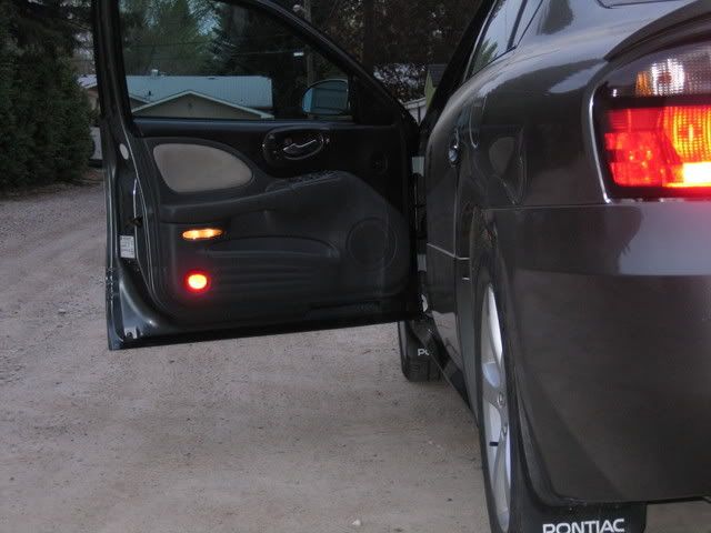
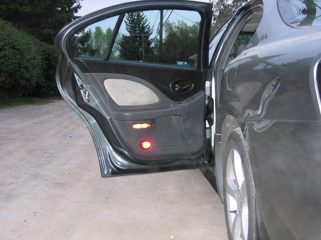
Adding Door Panel Courtesy Lighting - 2001+ BonnevilleThis process was completed on a 2004 GXP but should be similar (if not identical) for any 2001+ Bonneville. This doesn’t apply to the 2000 model year as these were standard equipment in those vehicles.
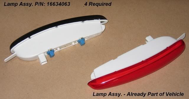
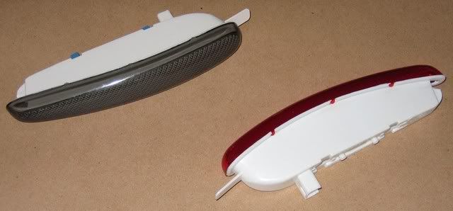
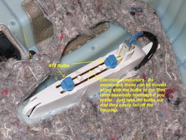
Here's what’s different:In 2001+ model year cars there are no wiring provisions in place. This means it isn’t as simple as just snapping in the new lamp assemblies. The lamp assemblies are different in 2000 being that they are smoked, not red. Also, the 2001+ lamps are only a shell whereas in 2000 they included the bulbs and electrical conductors. The lamps are a #74 incandescent bulbs. If desired, it would be possible to purchase the smoked colour assemblies and transfer the conductors and bulbs to the red assemblies. Physically the two assemblies are the same size and shape.
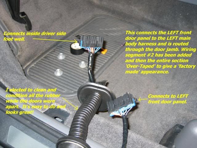
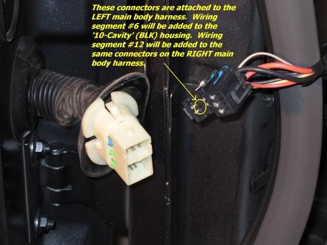
The advantage to using the parts I've outlined and following my procedure is that wiring will pass through the factory connectors. This is especially helpful where wiring passes between the body and door.
About the procedure:The project can be broken into several smaller segments. These are:
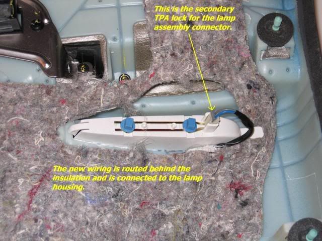
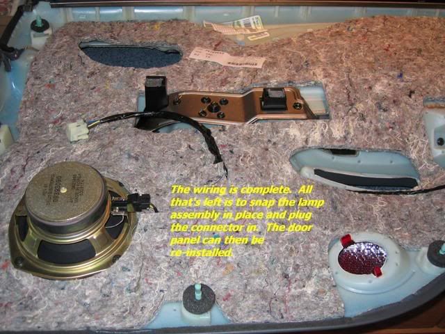
1. Add the lamp module to each door panel.
2. Add wiring to each door panel wiring harness.
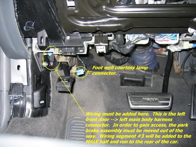
3. Add wiring from each door panel harness to the vehicle body harness.
4. Add wiring to the body harness for each door.
5. Make final connections to the courtesy lamp circuit under the rear seat.
About the lamp assemblies:The assemblies I used were for the 2000 model year Bonneville with the part number 16634063. Thanks to Harofreak00 for researching and providing this! You'll need one for each door. As stated, these come with the lamps and conductor rails. A separate connector plugs into the lamp assembly.
 About the wiring:
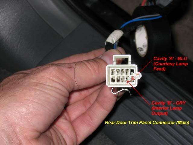
GM has specified that 0.35mm2 (SAE 22AWG) wiring be used. The colours are ‘Gray’ and ‘Dark Blue w/ White Stripe’. Gray was easy to acquire, but the dark blue with a white stripe was only available if I purchased a 100,000 foot roll. Needless to say, this wasn’t a reasonable option and a solid ‘Blue’ conductor was used instead.
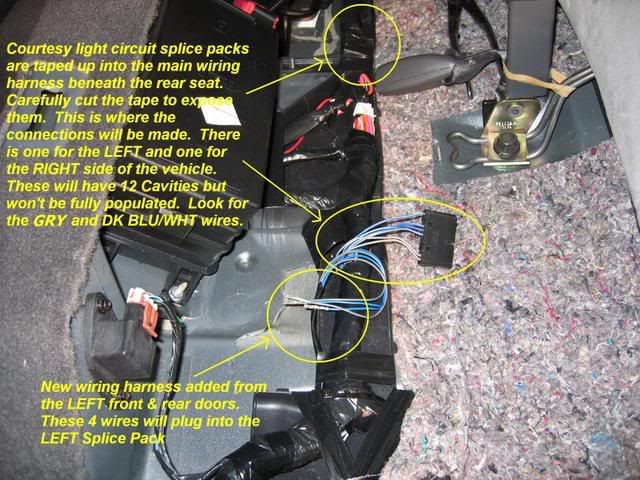
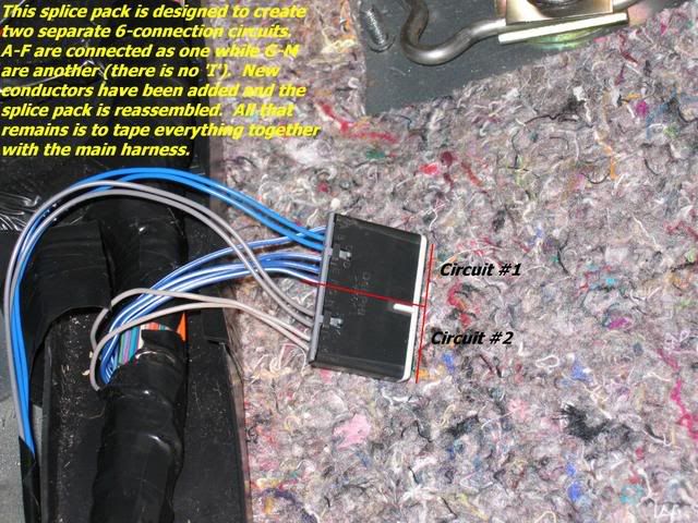
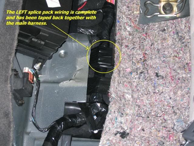
Connections into the courtesy lamp circuit are made under the rear seat by adding conductors to pre-existing splice packs. These are taped up as part of the main wiring harness that runs from the left to right side of the car and is just behind the rear power distribution centre. More details on this later.
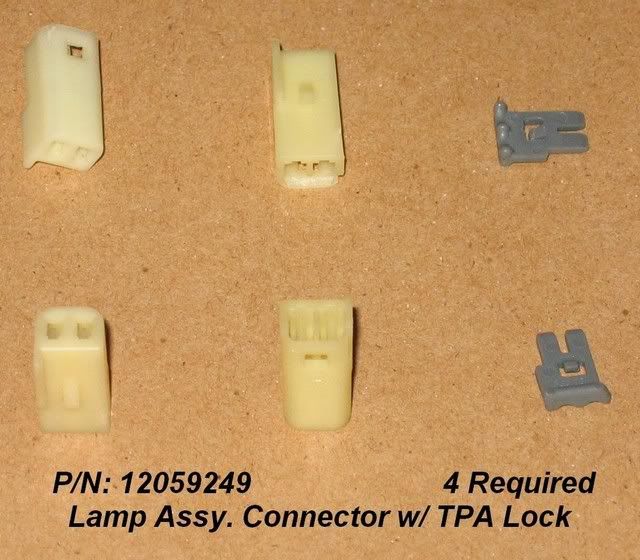
Required connectors NOT already in the vehicle:Lamp Assembly Connector
GM Part Number: 12059249.
2-Way Metri-Pack 150 Series Female Unsealed Connector (Colour: White/Natural)
Available at
http://www.mouser.com. If purchased here, the terminal position assurance (TPA) lock must be purchased separately, P/N: 15324070
An alternate source is an auto wrecker. These are the same connector as used for courtesy lights on any mid-late 90’s Bonneville.
 Building the wiring harness segments:
The following wiring segments are based on a 2004 GXP. There is no reason to believe they won't be the same as other 2001+ model year vehicles, however it is possible that GM production techniques changed causing a variance.
Each segment of wiring will require both a gray (‘GRY’) and blue (‘BLU’) conductor. Two wires and four terminals are required for each segment. A total of 12 segments (24 wires) must be built and added. The wire length specified is in inches unless otherwise specified (some measurements include feet and inches).
These lengths are for the wire itself BEFORE terminals are attached. The addition of terminals will increase the length of the specified measurements. See **Legend at the bottom of this section for further details.
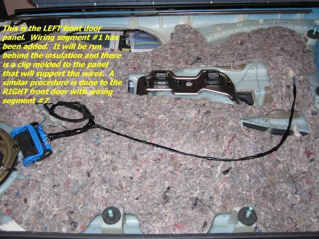
#1 – Left Front Door Trim Panel Harness (F-M)
[12064971] >-------------------- 25 1/4" --------------------> [15304701]
#2 – Left Front Door -> Left Body Harness (F-F)
[12191811] >-------------------- 46 1/2" --------------------< [12191811]
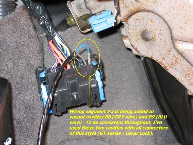
#3 – Left Body Harness -> Left Rear Splice Pack (M-F)
[15304701] <-------------------- 8' 4" --------------------< [12191811]
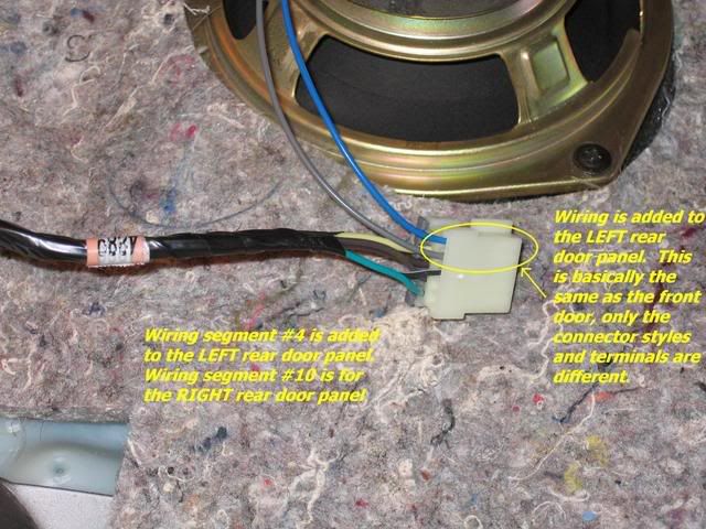
#4 – Left Rear Door Trim Panel Harness (F-F)
[12064971] >-------------------- 24 3/4" --------------------< [12064971]
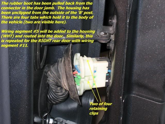
#5 – Left Rear Door -> Left Body Harness (M-M)
[12059894] <-------------------- 27" --------------------> [12059894]
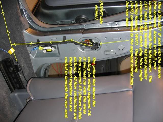
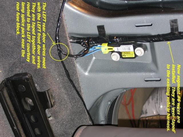
#6 – Left Body Harness -> Left Rear Splice Pack (F-F)
[12191811] >-------------------- 5' 2" --------------------< [12191811]
#7 – Right Front Door Trim Panel Harness (M-F)
[15304701] <-------------------- 23 5/8" --------------------< [12064971]
#8 – Right Front Door -> Right Body Harness (F-F)
[12191811] >-------------------- 47 3/4" --------------------< [12191811]
#9 – Right Body Harness -> Right Rear Splice Pack (M-F)
[15304701] <-------------------- 9' 1" --------------------< [12191811]
#10 – Right Rear Door Trim Panel Harness (F-F)
[12064971] >-------------------- 24 1/2" --------------------< [12064971]
#11 – Right Rear Door -> Right Body Harness (M-M)
[12059894] <-------------------- 26 3/4" --------------------> [12059894]
#12 – Right Rear Body Harness -> Right Rear Splice Pack (F-F)
[12191811] >-------------------- 72" --------------------< [12191811]
**Legend:
M: Male, F: Female
Terminal P/N: [########]
Female Terminal: >----- or -----<
Male Terminal: <----- or ----->
Harness segments #1, 4, 7 & 10:
These are all located entirely within their respective door trim panels.
Harness segments #2, 5, 8 and 11:
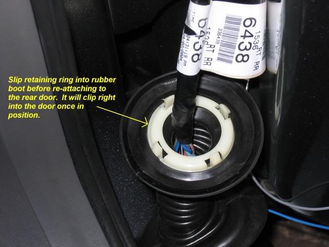
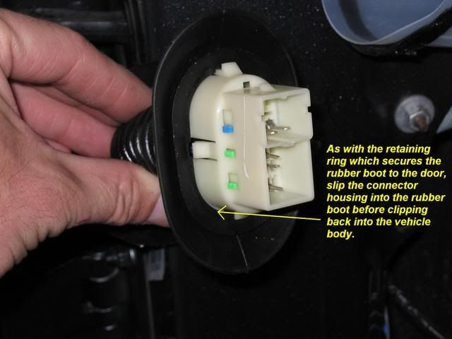
These all run from their respective doors, through the door jamb and into the vehicle for connection to the main body harness.
Harness segments #3, 6, 9 and 12:
These all run within the vehicle and terminate under the rear seat where the final connection is made into the courtesy lamp circuit.
The following table shows the individual connector terminals used. These are all Delphi/Packard Electric part numbers. At the time this thread was posted, all necessary parts (except the lamp assemblies and wire) are available at
http://www.mouser.com.
--------------------------------------------------------
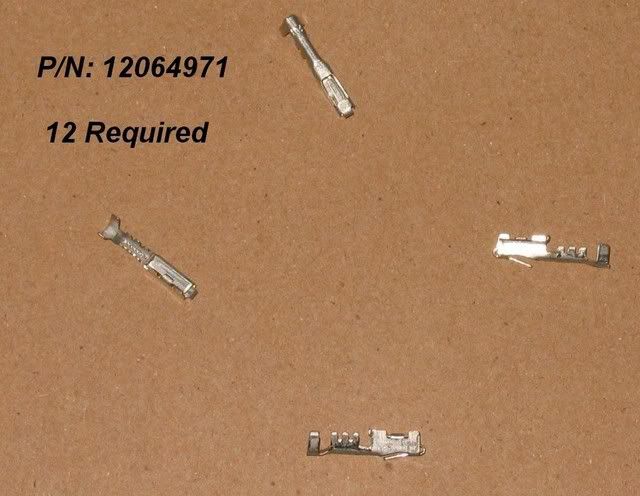
P/N: 12064971 (Total of 12 Required)
Metri-Pack 150 Series Female Tin Terminal
Used in Wiring Segments:
#1 – Quantity of 2 required.
#4 – Quantity of 4 required.
#7 – Quantity of 2 required.
#10 – Quantity of 4 required.
--------------------------------------------------------
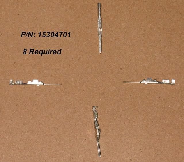
P/N: 15304701 (Total of 8 Required)
GT 150 Series Male Tin Terminal
Used in Wiring Segments:
#1 – Quantity of 2 required
#3 – Quantity of 2 required.
#7 – Quantity of 2 required.
#9 – Quantity of 2 required.
--------------------------------------------------------
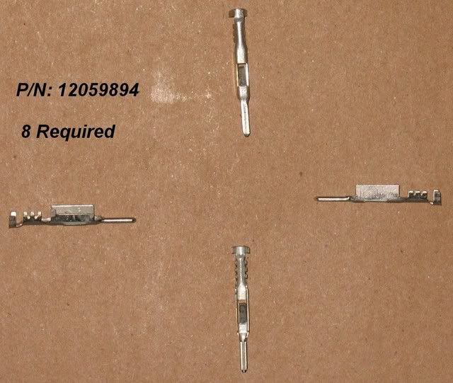
P/N: 12059894 (Total of 8 Required)
Metri-Pack 150 Series Male Tin Terminal
Used in Wiring Segments:
#5 – Quantity of 4 required.
#11 – Quantity of 4 required.
--------------------------------------------------------
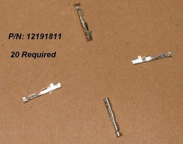
P/N: 12191811 (Total of 20 Required)
GT 150 Series Tin Female Terminal
Used in Wiring Segments:
#2 – Quantity of 4 required.
#3 – Quantity of 2 required.
#6 – Quantity of 4 required.
#8 – Quantity of 4 required.
#9 – Quantity of 2 required.
#12 – Quantity of 4 required.
--------------------------------------------------------
Crimp tool used for assembly:
--------------------------------------------------------
PREPARING FOR INSTALLATION:To access all required areas, the steps below must be completed. Both the removal and re-installation directions are provided.
STEP #1: DISABLE SUPPLEMENTAL INFLATABLE RESTRAINT (SIR) SYSTEM
Extreme care must be used when working on or around the Supplemental Inflatable Restraint (SIR) system. Failure to do so can result in serious injury, death and/or unnecessary repairs. Do not attempt these procedures unless you are familiar with these systems and procedures.DISABLING (AS PER THE GM SERVICE MANUAL):1. Position the steering wheel so that the front wheels are pointing straight forward.
2. Turn the key to the OFF position and remove it from the ignition.
3. Remove the rear seat cushion (procedure below).
4. Remove the rear fuse block cover.
5. Remove the SIR fuse.
6. Remove the LEFT & RIGHT 'B' post garnish moldings (procedure below).
7. Remove the connector on each of the SIR sensors. These are mounted at the base of each 'B' post on the interior of the vehicle. They are labelled as part of the SIR system and will have yellow connectors. You will need to remove the CPA (connector position assurance) lock before the connector can be released and unplugged. ** DO NOT WORK ON THESE CONNECTORS BEFORE REMOVING THE SIR SYSTEM FUSE **
RE-ENABLING SIR SYSTEM (AFTER ALL INSTALLATION STEPS COMPLETE):1. Follow above steps in reverse. Be sure not to reinstall the SIR system fuse until the 'B' post garnish moldings have been replaced.
2. Once all steps are complete, use CAUTION and reach into the vehicle, insert the key and turn to the ON position. The AIRBAG light will illuminate and then turn off.
STEP #2: TRIM REMOVAL:1. Remove the kick panel under the dash by the driver and front passenger feet. See the 'Procedure w/ Pictures' section below for instructions.
2. Remove the carpet retainers just inside each of the four doors.
 CARPET RETAINER REMOVAL:
A. Open the door.
B. Unsnap the carpet retainer.
C. Remove the carpet retainer from the floor.
CARPET RETAINER INSTALLATION:A. Install the carpet retainer to the floor.
B. Snap the carpet retainer into place.
C. Close the door.
STEP #3: REMOVE THE LEFT & RIGHT 'B' PILLAR TRIM PANELS: 'B' PILLAR TRIM PANEL REMOVAL:
A. Remove the front and rear carpet retainers.
B. Disable the SIR system (Zones 2 & 6). There are airbag sensors behind these panels.
C. Pull out on the centre trim panel to disengage the clips. Use caution as this is a two part molding. There is a plastic weld half way down (where the color changes) that can be broken if care isn't exercised.
'B' PILLAR TRIM PANEL INSTALLATION:A. Position the garnish molding in place. Position the weatherstrip over the edge of the molding. Press the molding in place to engage the retaining clips.
B. Install the front and rear carpet retainers.
C. Enable the SIR system (Zones 2 & 6).
STEP #4: REMOVE THE REAR SEAT CUSHIONSEAT CUSHION REMOVAL:A. Pull straight up on the lower forward edge of the seat cushion.
B. Remove seat cushion from the car.
SEAT CUSHION INSTALLATION:A. Place seat cushion in car. Ensure all seat belts are positioned for access.
B. Press downwards on forward portion of seat cushion to snap in place.
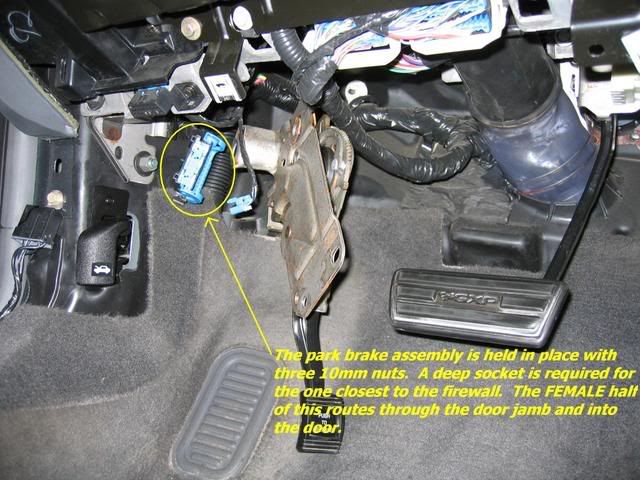
STEP #5: REMOVE ALL FOUR DOOR TRIM PANELSSTEP #6: REMOVE THE PARK BRAKE PEDAL ASSEMBLYTo gain access to the ‘Body Harness -> Left Front Door Harness’ connector, the park brake pedal assembly must be moved out of the way. This is done by removing 3 nuts securing it in place. You’ll need a 13mm deep socket.
PROCEDURE WITH PICTURES: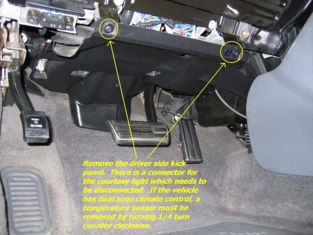
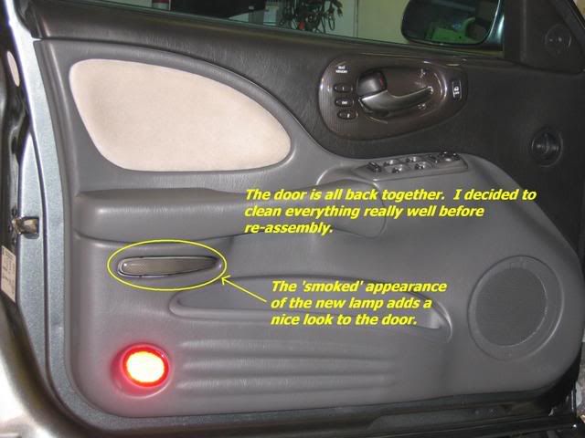
 PROJECT COMPLETE: