Years 1987 to 1999 are the same with the only difference is that with an oil pressure gauge there is a sender used instead of a switch. The sender is nothing more than a variable resistor that controls the gauge. Without the gauge, there is a set of normally closed contacts that are used to illuminate the light.
The concern in this topic is the second set of contacts in the oil pressure sender / switch unit. They are normally open and set to close when the oil pressure reaches 4 psi. This circuit is used to supply a second source of power to the fuel pump. Basically it is a back-up if the fuel pump relay fails.
First we will go over the fuel system electrical circuit:
When ignition is turned on, the ECM / PCM energizes the fuel pump relay and remains on as long as the following are true:
1. Engine is cranking or running
2. ECM / PCM is receiving fuel control pulses
If the pulses are lost, the ECM / PCM de-energizes the fuel pump relay after 2 seconds of the loss.
The fuel pump has a direct link from a primer connector in the engine compartment. This connector is behind the battery and is green in color and attached to a grey (87-91) or red (92-99) wire. If 12 volts is applied to this it will energize the fuel pump. On the 87-91 it is a direct link, on the 92-95 it goes through closed contacts on the fuel pump relay.

If the original problem is "cranks, but will not run", then follow this:
Set up: engine idling at operating temperature, oil pressure normal
----1. remove fuel pump relay
----2. does engine continue to run?
---------a. yes - no problem in electrical circuit
---------b. no - faulty oil pressure switch
The following is the troubleshooting proceedure from the FSM for the 1995.
If there is no fuel pressure then turn ignition off and using a fused jumper apply battery voltage to the test connector mentioned above. Listen for fuel pump running and monitor fuel pressure gauge. There are three states available at this point: Pump running no pressure, pump not running no pressure, or pump running proper pressure.First condition leads to a problem in fuel delivery, not electrical.
Second condition:
1. Turn ignition on
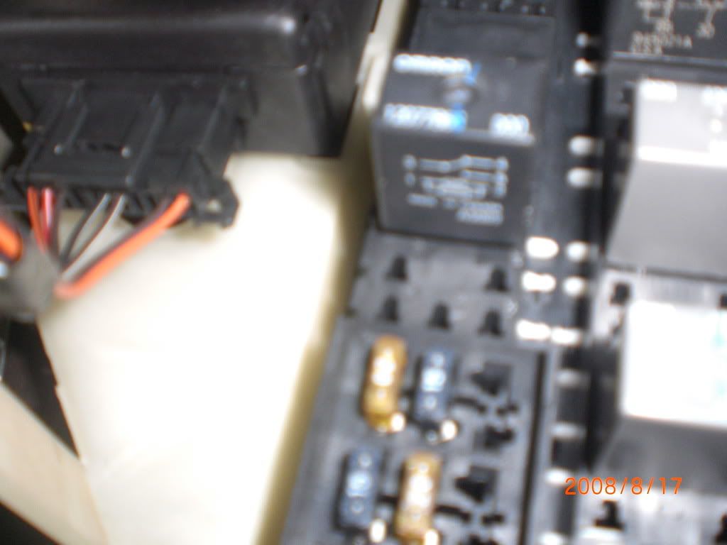
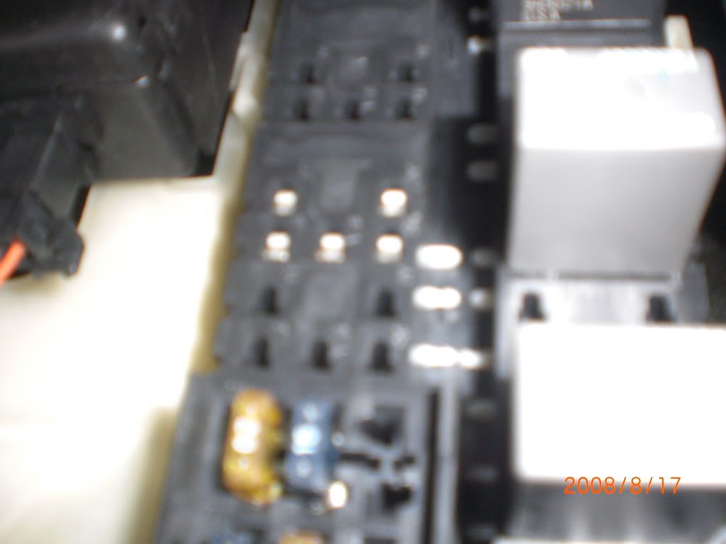
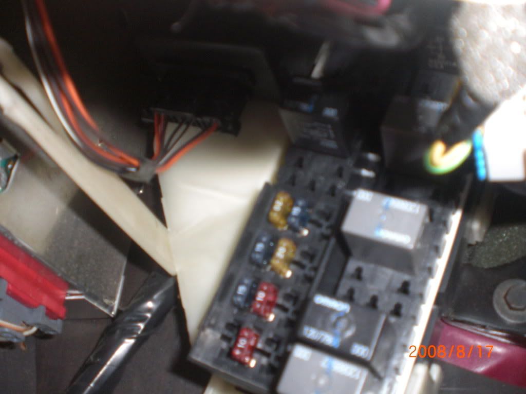
2. Remove relay and install jumper between cavities 87 and 30.
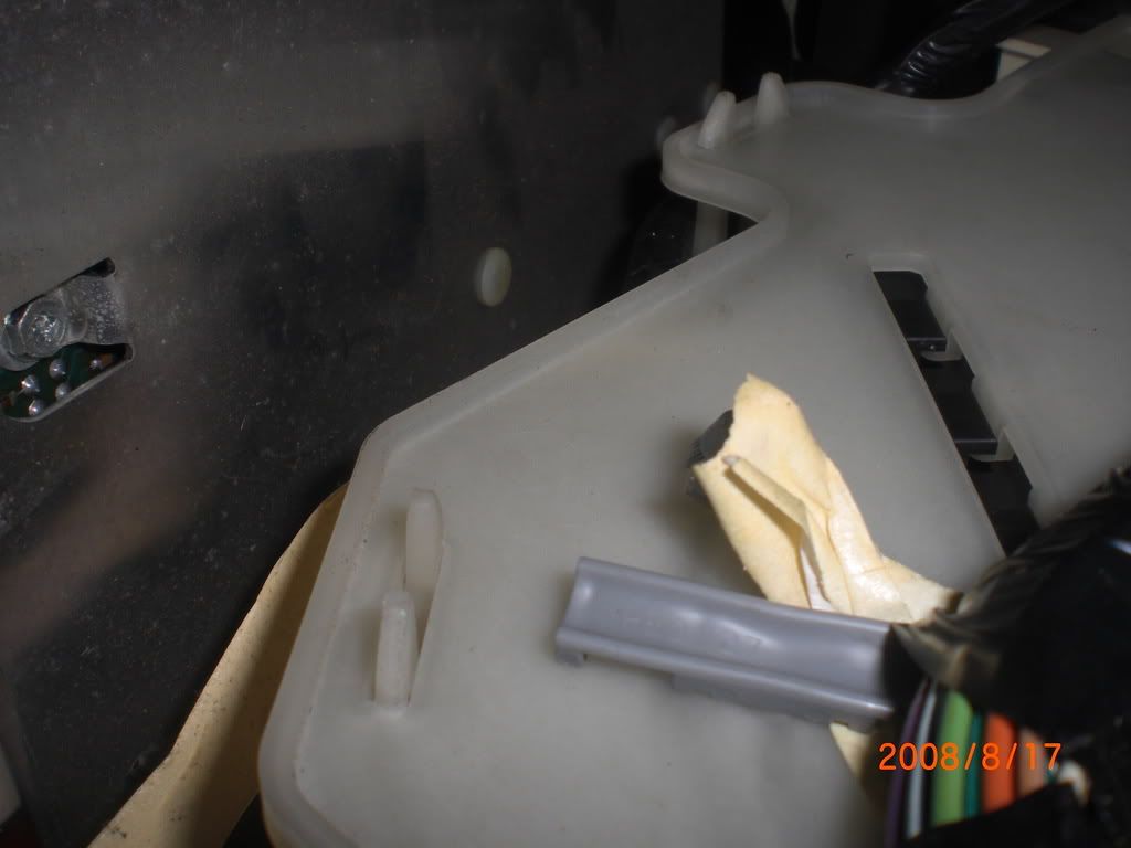
It is a tight fit and there is a plastic panel in the way that holds a few wiring harnesses in.
You can squeeze the tabs and it will allow you enough room to pull it out of the way to see the socket.
3. If you have pressure then the test connector circuit is faulty.
4. If no pressure then there is a problem in the wiring to the pump or the pump is bad.
Third condition:
1.Checking the fuel pump relay ignition feed and ground circuits
-a. Disconnect the jumper installed earlier
-b. remove relay and insert test light in cavities 87 and 86
-c. With ignition on and engine off is light on?
2. Determining if the PCM is controlling the circuit
----a. No light from previous step
-------1. test light between ground and relay cavity 87
-------2. light on means an open in ground circuit to relay
-------3. light off means either a bad fuse or an open in the feed circuit to relay cavity 87
----b. Light on from step 1. c.
-------1. ignition off
-------2. test light between cavities 85 and 86
-------3. ignition on and watch for light to light up for 2 seconds, if light works then either faulty relay or bad relay connections
3. Checking circuit between PCM and relay
----a. Ignition off
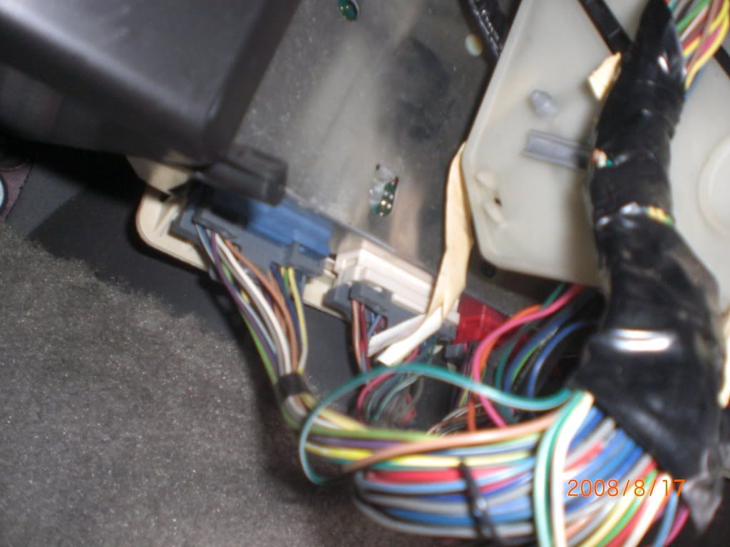
----b. Test light between ground an PCM white C-D connector WD-16
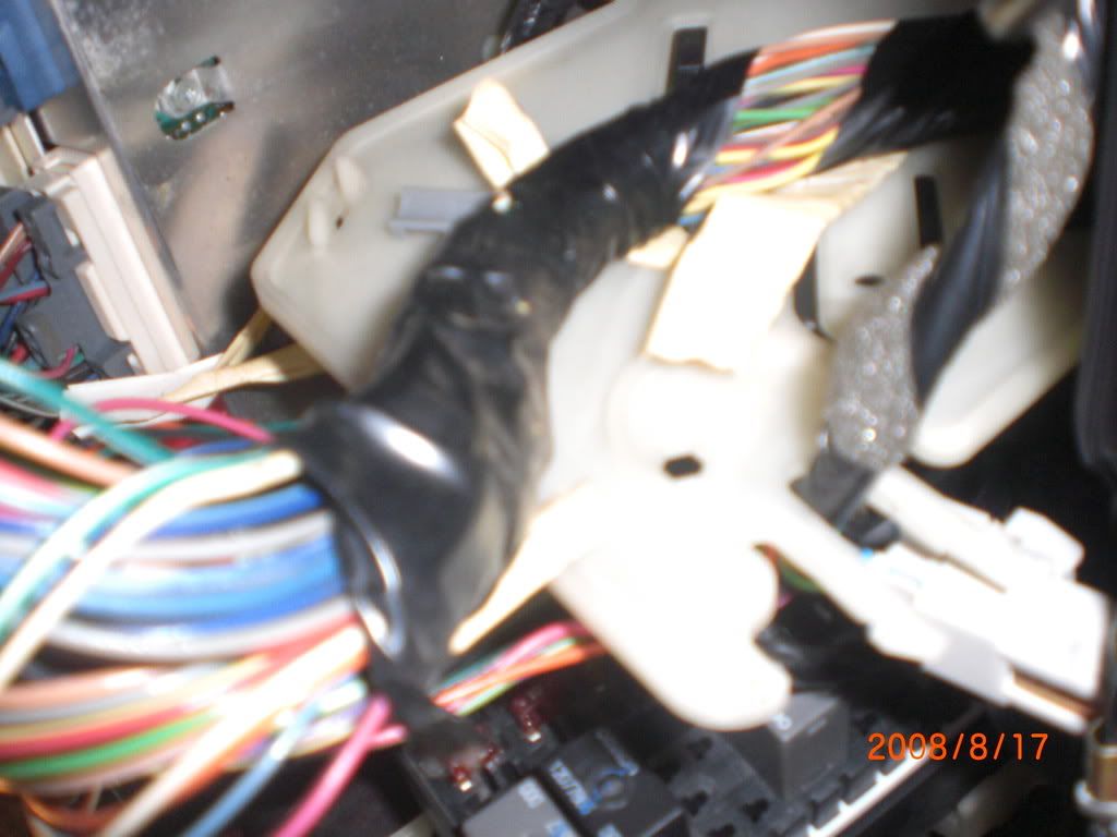
The White connector is in the middle and the term WD-16 refers to white connector, row D and pin 16.
In the picture it is the pin on the right end of the white connector closest to you. Dark green / white wire.
----c. Ignition on
----d. If light is on for 2 seconds then open incircuit between PCM and relay
--------1. If light is not on
-----------a. disconnect PCM white C-D connector and connect test light between battery voltage and terminal WD-16
-----------b. light on indicates a faulty PCM connection or faulty PCM
-----------c. no light indicates a short to ground in the circuit between the PCM connector and the relay.


