Turn Signal MirrorsWhen I started looking at adding signal mirrors I spent a lot of time researching possibilities which ultimately yielded no acceptable results. Since the LeSabre is close, I considered transplanting mirrors but the base doesn’t line up with the holes on the Bonneville. Alterations to the doors beyond what I felt was reasonable, partially because the base is physically larger than our cars, would have been required. I also looked at using mirror glass from another GM vehicle with this option. I found that Bonneville (mirror) glass is just that… Bonneville glass. It is not used on any other GM product. I also wasn’t able to find anything with a shape and size that was adequate. I started looking aftermarket and found some turn signals that will stick on the face of existing mirrors and wiring is run around behind. There were also some built into stick-on wide angle mirrors. None of these options was of any interest. Muth Mirror Systems who happens to make many of GM’s mirrors does sell aftermarket kits but not for the Bonneville. When I contacted them, their sales rep sent me an e-mail indicating they currently have no intent on making a Bonneville kit due to lack of interest. Gentex and Donnelly also make mirrors for some GM vehicles although nothing applicable here. Since it really grates on my nerves when someone tells me I can’t do something, I decided to get down to business and make some myself.
Now on to the mod…
*** Always wear appropriate safety glasses and gloves when working with the mirrors ***This process can be achieved by modifying either heated or non-heated mirrors (although non-heated are definitely easier).
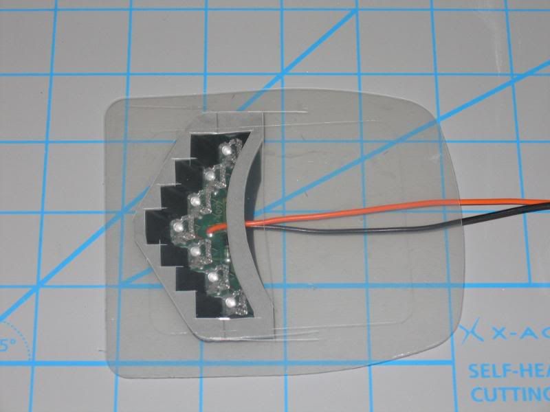
I did purchase a pair of very nice LeSabre mirrors from Schram Auto Parts ($200.00/pair). It was a shame to dissect them because you wouldn’t know they weren’t brand new. Not a scuff or swirl mark on them. Needless to say, I required the LED assemblies attached to the back of the mirror glass (held on with two-sided mounting tape).
In order to start, I removed the mirror glass (including mount) from the car. Much care is required because if you pull or twist at the wrong angle you WILL crack the mirror. I had a test mirror kicking around from my ’02 SE which had the housing damaged in a collision. My point is proven by the fact I cracked the glass doing just what I said not to do.
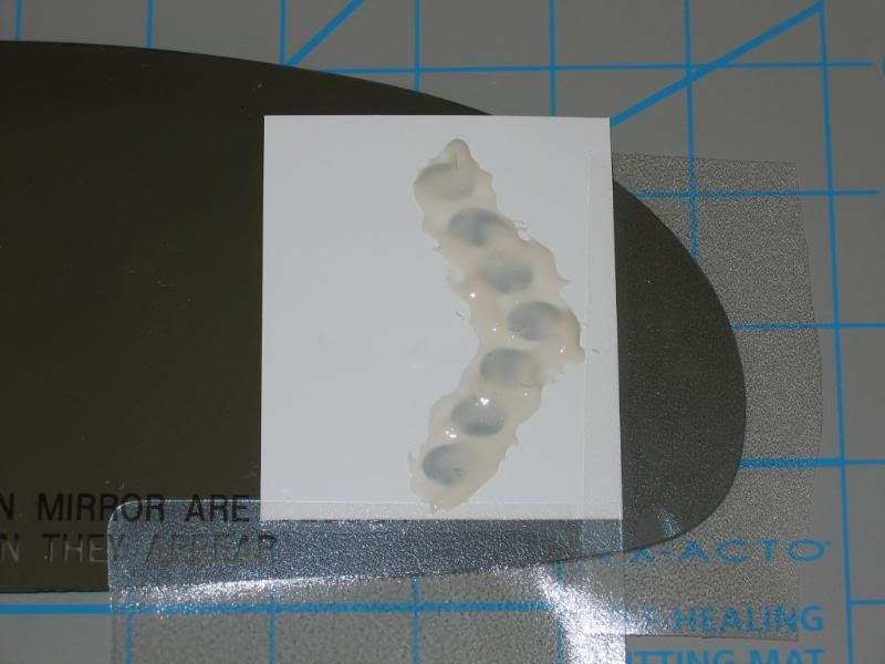
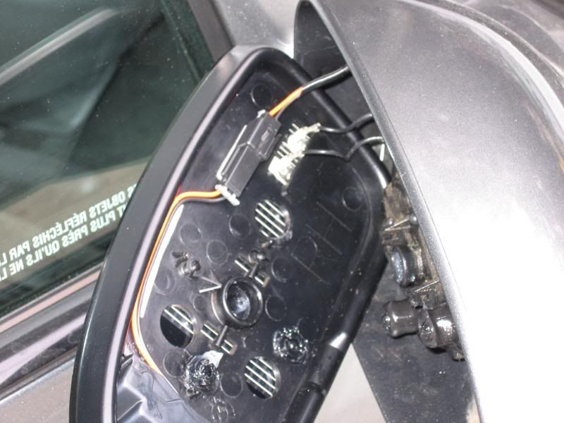
Once off, the glass must be carefully separated from the mounting frame. In the case of the 2K+ Bonneville, it is held on by three 1” diameter dabs of silicone and two 1”x 1” double sided mounting tabs (used to hold the glass until the silicone sets). I was able to very carefully insert a long X-Acto knife blade between the edge of the glass and the edge of the mount. I worked my way around the outside of the mirror cutting through the foam pads and silicone. It’s important not to flex the glass but the frame does have some give. Gradually you can work towards the centre and the glass will separate. The heating element is very thin and well adhered to the glass but can be damaged if careless. This didn’t pose a problem for me. Once separated, clean off as much silicone and remains of the mounting tabs as possible. As long as the surface is basically smooth, you don’t have to get too crazy here.
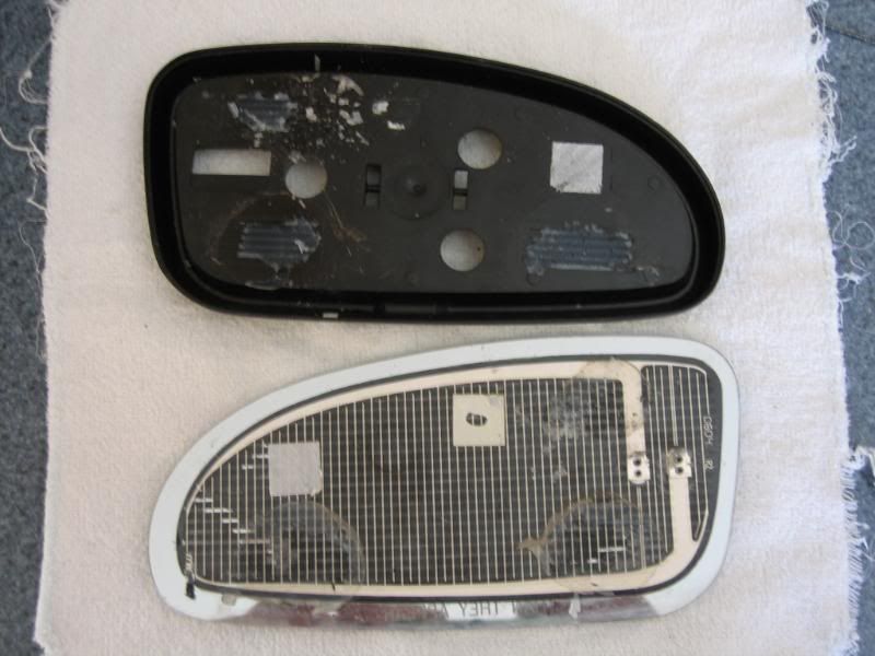
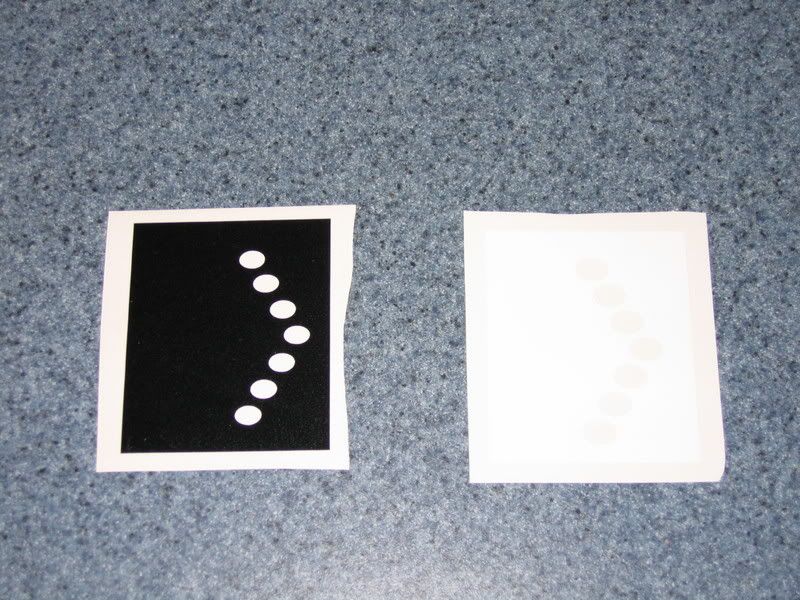
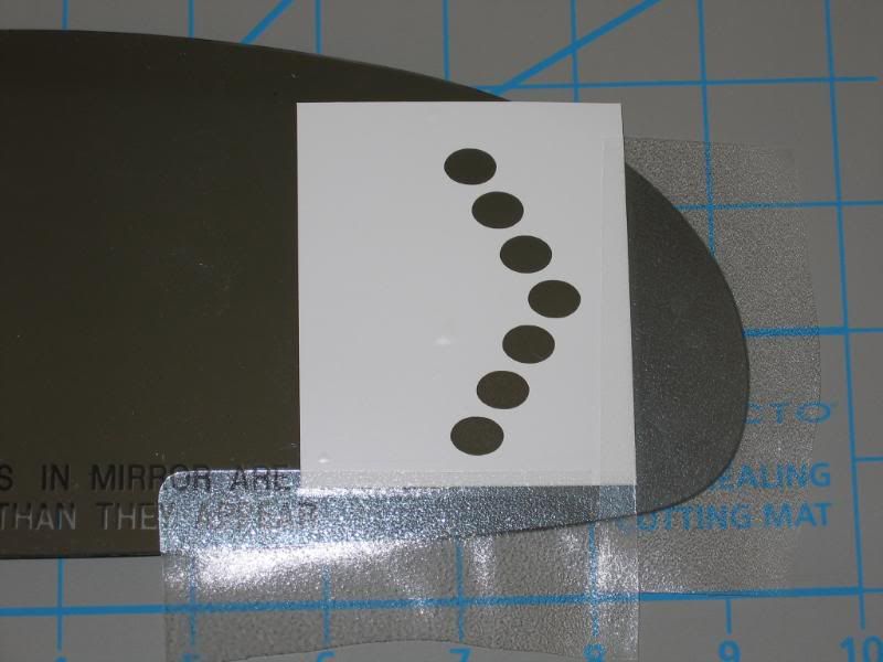
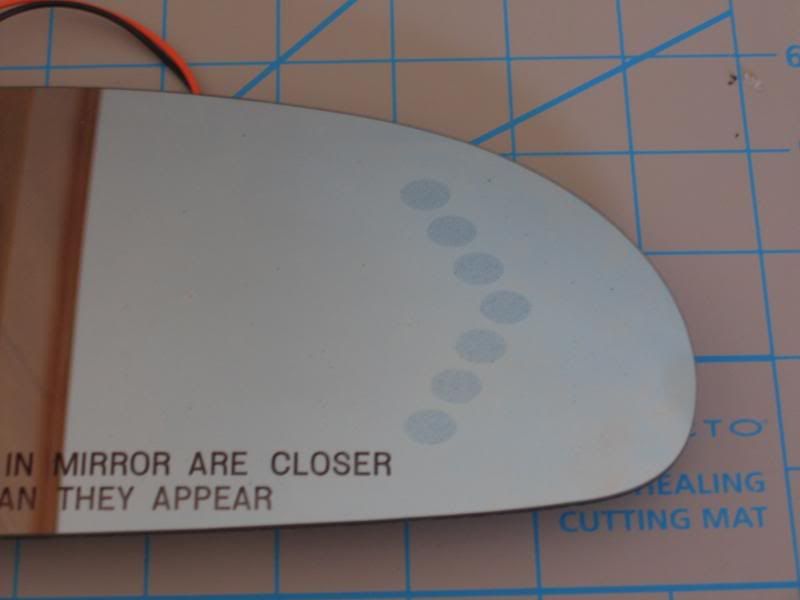
Looking at the OEM mirrors with the signal option, there are seven ovals on the face which allow light to pass through the reflective coating. On the rear of the mirror, there is a similar pattern of ovals, however these are slightly smaller and act as a mask to ensure light only passes in the intended pattern. Since the LED assembly is very bright, the image will be blurred without the rear mask since some light can pass through the mirror, reflective coating or not. I used PhotoShop to create templates and sent them off to NHolds who made some computer cut decals for me. The decal (light mask) applied to the back of the mirror will remain permanently and is black in colour. The etching mask (more on this later) applied temporarily to the front and with the slightly larger ovals was made of a white material. I must say Ryan did an awesome job of these.
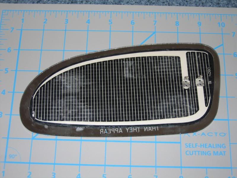
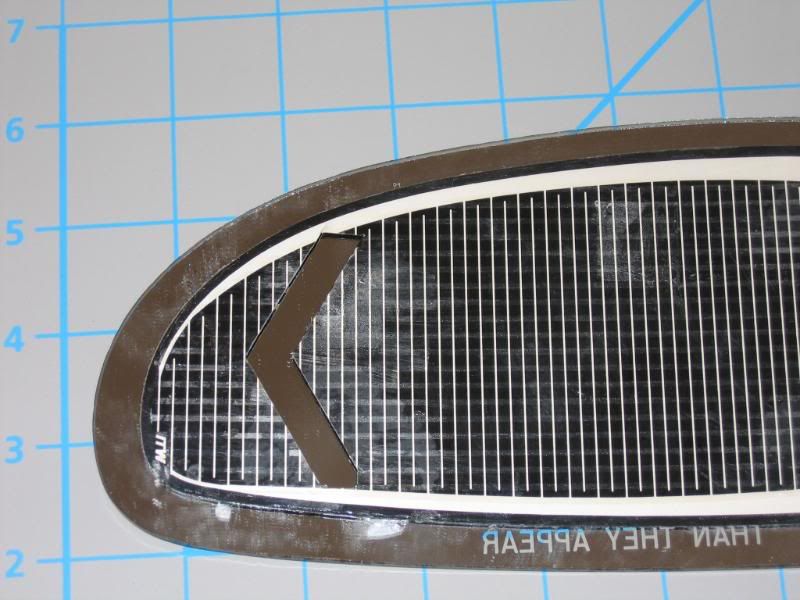
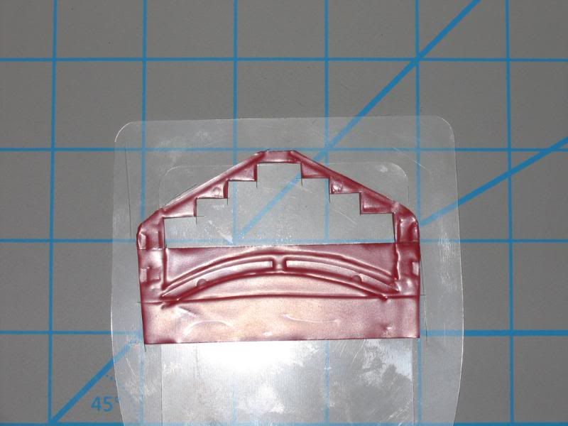
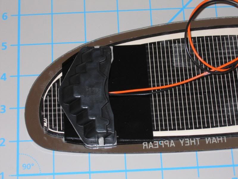
Next I needed to cut a chevron pattern in the heating element for the LED’s to shine through. Doing this will render a portion of the element non-functional but done carefully will limit this. Looking at the element you’ll notice thick white borders across the top and vertical white lines alternating from the top and bottom. My understanding is that these carry the current required to heat the element so you really want to limit damage to these. Definitely don’t cut the thick traces at the top and bottom or everything beyond that point won’t function (using the wire terminals as a starting point).
I used a heat gun to warm the glass and used a razor blade to lift off about 3.5 inches of the heating element. I put a non-stick backing between the element and the glass so when I made the cut for the chevron I wouldn’t scratch the back of the glass. I used the backing from expired defibrillator pads. These worked great since they were thick plastic and would peel away from the element when I was done with no effort at all. I suspect most people won’t have access to these so an alternative may be needed. Be careful what you use because these elements will stick to most plastics and similar surfaces. This is a great time to clean the glass well where the element was originally adhered.
After I cut the chevron pattern out (I used the black mask decal as a guide for placement and size), I removed my backing from the element and stuck it back onto the mirror. I applied the black mask decal over the chevron cutout.
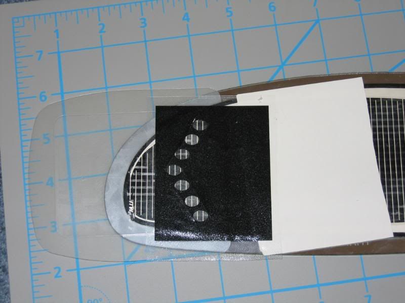
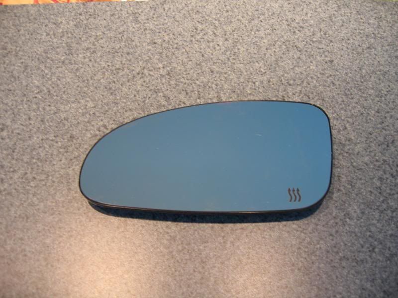
I made mention of a temporary etching mask earlier which is applied to the front of the mirror. I originally didn’t realize the reflective coating on these mirrors is on the front, not the back of the mirrors. Although some light can pass through the mirror even with the reflective coating, it is limited. This is where the second, white coloured decal comes in. Holding the mirror up to a light source, I applied the white decal to the face over top of the chevron patterned ovals now shining through from the back. Alignment is very important for a professional looking job. It is absolutely crucial to ensure the decal is well adhered to the glass. I used a good glass cleaner first to remove finger prints and other contaminants.
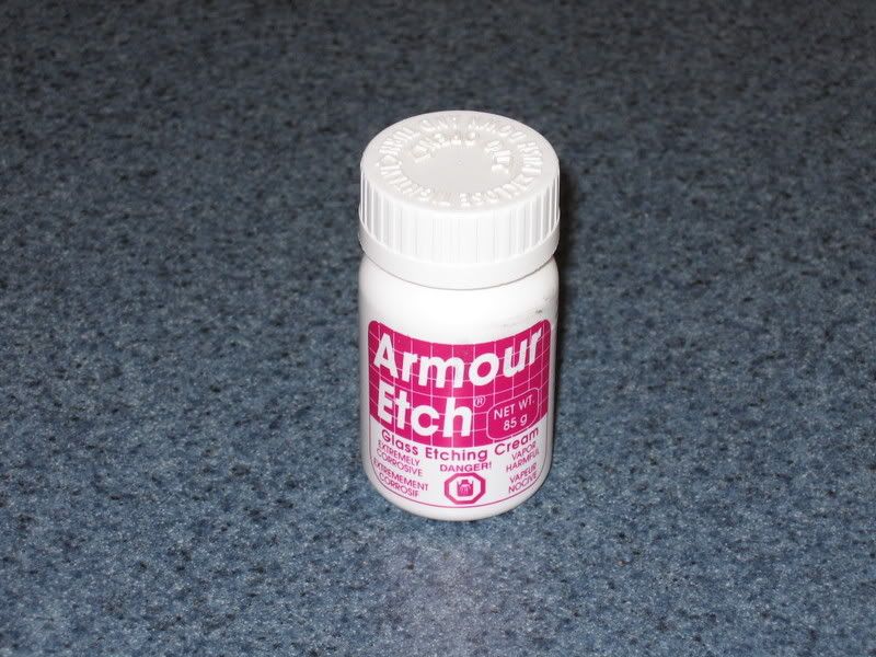
I used a glass etch paste to remove some of the reflective coating. It’s important not to remove all of it. Even the OEM mirrors have a ‘grid’ type pattern to limit the light to some extent. By etching the glass, some of the coating can be left on limiting the light and at the same time protecting the ability to see in the portion of the mirror which was etched. I used a Q-Tip to apply the paste. My etch time was about five minutes with some effort rubbing the spots with the swab. I may have outdated paste because it seemed to take longer that the glass shop led me to believe it would. Rinse very thoroughly with water afterwards. If needed more etch paste can be applied so it is better to go is short increments (a couple of minutes at a time). Also, do both mirrors at the same time so the etching will be similar between the two. You can see the finished result in my photo. It doesn’t look etched very much but it sure lets the light through. When you’re happy, peel off the etch mask decal.
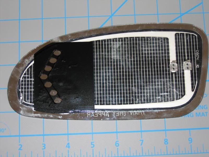
Next it’s time to mount the LED assemblies. I used 3M outdoor mounting tape (two strips side-by-side for adequate width). I pressed LED assembly firmly against the tape (backing still in place) and then used a knife to cut the pattern to fit the housing. I used my non-stick backing pads again as a working surface. Before sticking these to the back of the mirror, there are a couple of things you’ll need to know. The LED’s in the assembly are mounted at an angle so as to point towards a vehicle beside you, not straight back. The entire purpose of these is to warn drivers of your intent to change lanes who may not be able to see your rear signal light. Having said this, mount the assembly so the LED’s shine through the oval cutouts at an angle. If possible, dry fit and test before actually sticking them to the mirror. Again, alignment if critical.
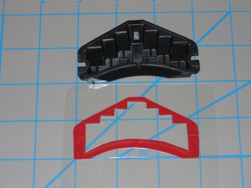
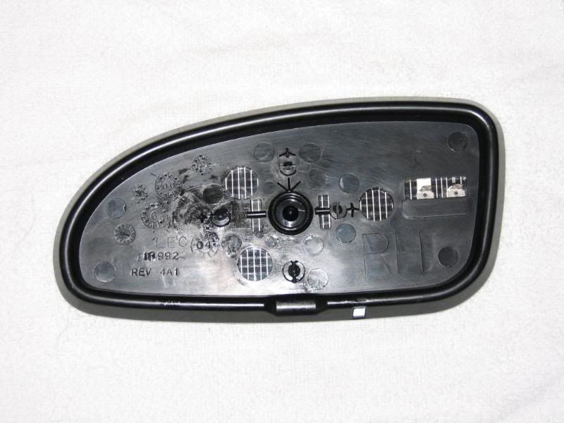
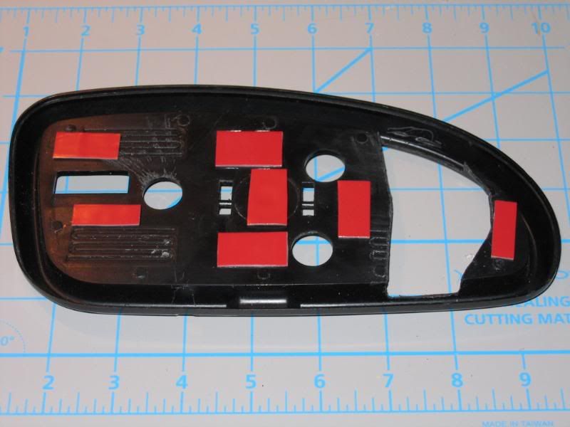
Next, the mount must be modified to provide clearance for the LED assembly. I found my Dremel tool to be invaluable here. You need to be certain not to affect any areas where there are pivot points or you won’t have an adjustable mirror anymore! This should also be a consideration when planning where to cut the heating element. Angles and alignment here is very important. It’s possible you may need to remove the element completely and move it slightly towards the outer edge of the mirror (although I didn’t need to do this with mine). You have to consider where you can most safely cut the element making sure it isn’t too close to the centre ultimately affecting safe modification of the frame. A little trial and error here is okay. Don’t make too big a hole to start. It’s much more effective to start smaller and enlarge as needed. Don’t make it any bigger than necessary.
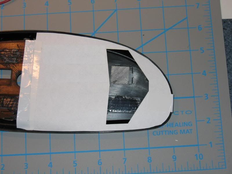
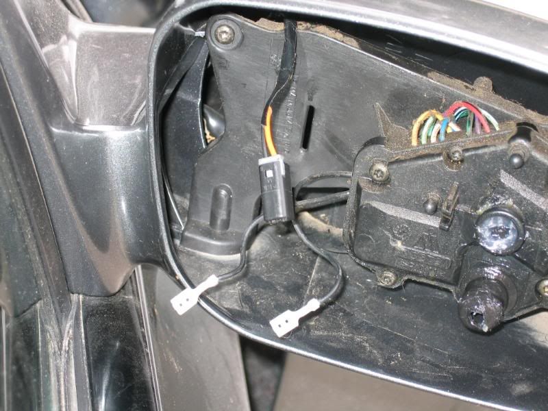
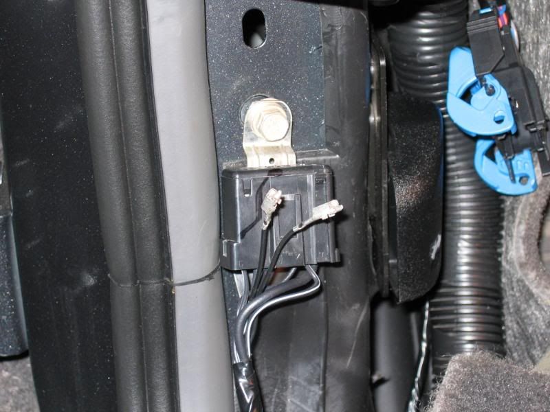
To complete the mirror itself, it must be remounted to the frame. I chose not to use silicone and attached it with small pieces of the 3M mounting tape instead. This tape is very strong and I’m not concerned at all that it will let go. Since you will need to put a reasonable amount of pressure on the front of the mirror to reattach it to the car, it is important to ensure good support behind the glass wherever there is a point the frame will snap to the adjuster assembly. The right side is shown, but the left is similar. See above photo for important tape placement.
I used a fairly standard automotive electrical connector from GM vehicles found at the wrecker for wiring. This is simple and inexpensive. The mirror assembly itself is now complete.
*** IMPORTANT***
When you snap the mirror back onto the adjuster, use a sanding block with a couple of layers of paper towel (or another soft but thin material) to protect the glass. This will distribute the force applied more evenly across the surface of the glass and decrease the risk of it cracking.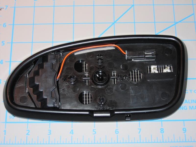
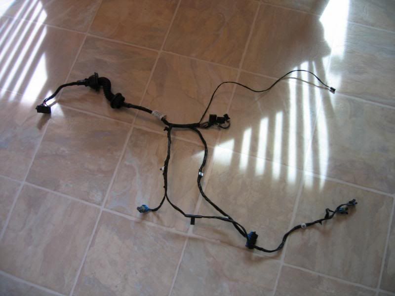
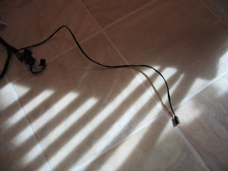
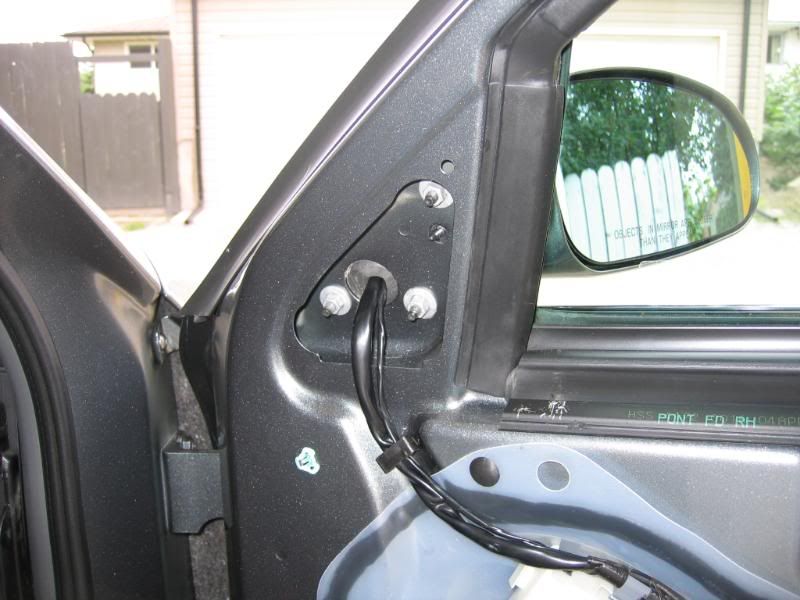
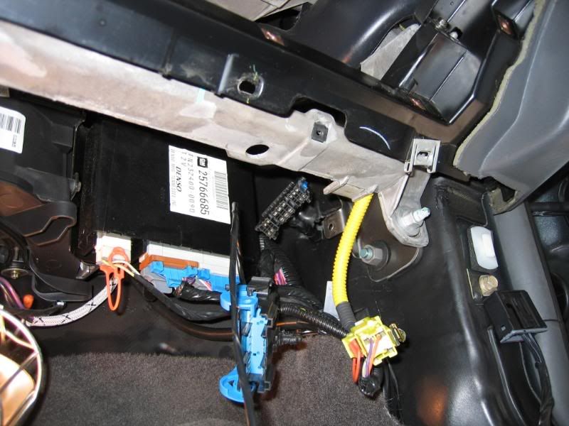
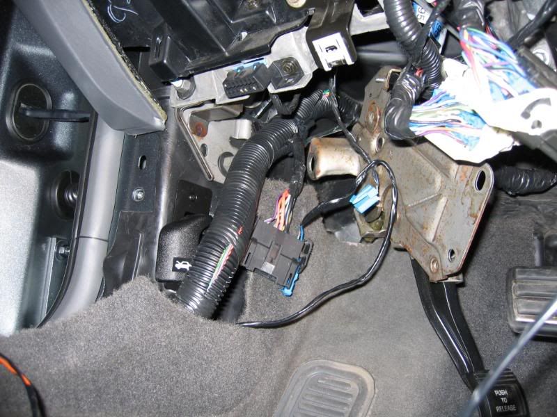
Adding wiring into the doors is a whole other story… This was a lot of work as well. I removed the wiring harnesses from the front doors completely. I added applicable wiring segments and then re-installed them. I had gone through this before when I added courtesy lighting to my doors. Had I been smart then, I would have added some additional wires for future use at that time. Needless to say, I added an extra pair this time around. These wiring harnesses connect inside the left and right foot wells. In the case of the left, I had to move the park brake assembly out of the way. I ran wiring from these connectors and tied the ground into the splice pack just inside the front of the driver door. I tied the signal light supply wires into C200 which is a white 40 pin Lever Lock style connector just in front of the steering column under the dash. This may vary from year to year in the 2K+ model.
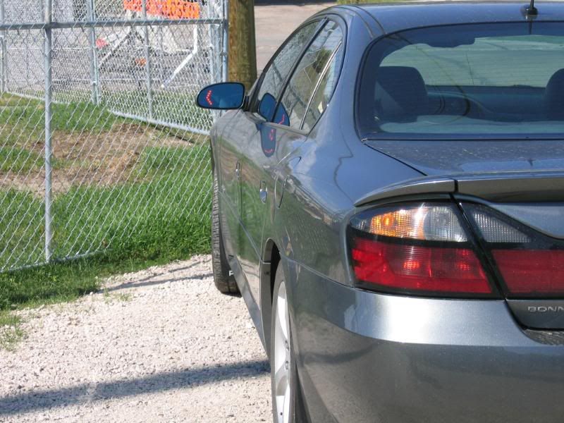
So this is basically it… Many hours of research, lots of money spent and many tedious tasks not to mention a few sore muscles from being contorted underneath the dash. It was challenging, but interesting at the same time. I'm glad I went ahead with this.
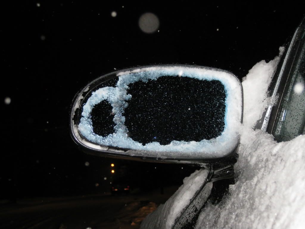
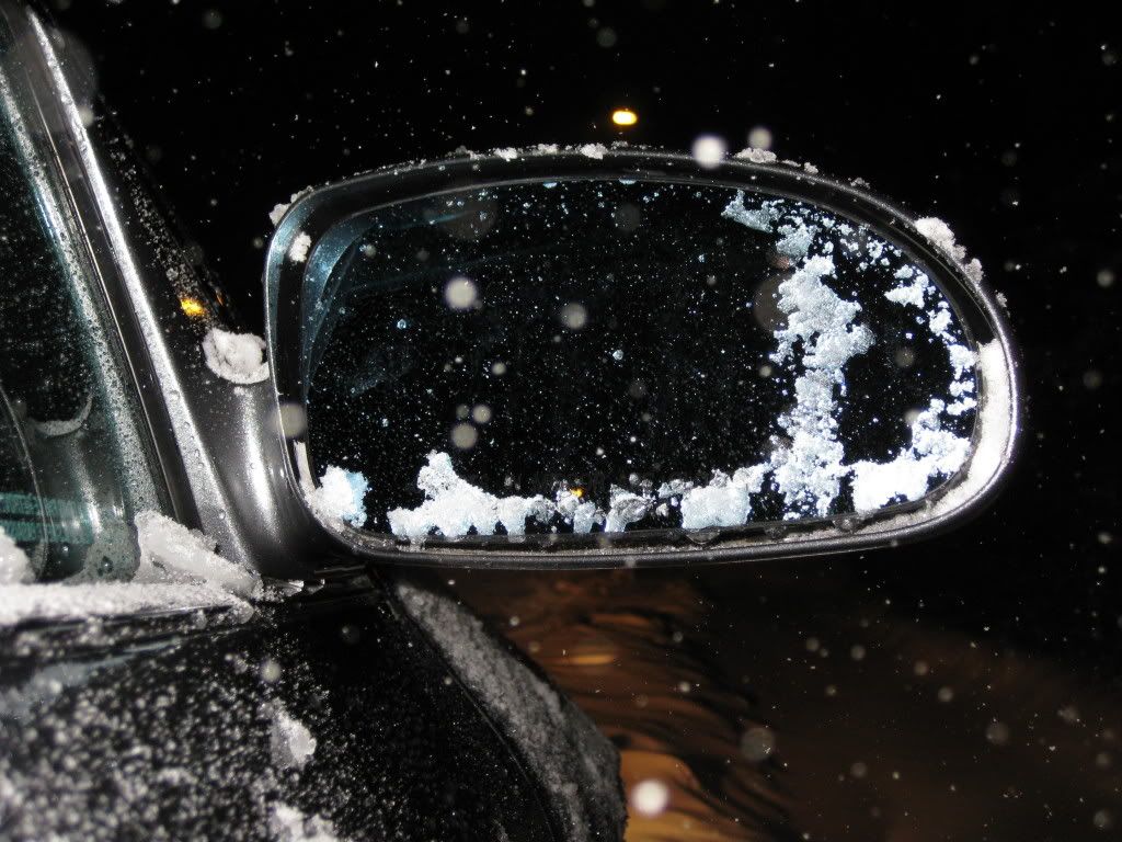
Now for a winter picture... You can see that by modifying the heating element carefully there is still function retained beyond the location of the LED assemblies. Failing to do this may result in limited frost, snow or ice clearing.
_________________
 Bose Luxury Sound System w/Touch Screen Navigation
, Addition of Factory XM, 2005 MY Antenna, OnStar Upgrade (3G),
RainSense Wipers, Backup Camera, '00 Style Door Panel Courtesy Lights,
Heated Washer Solvent, 2X Remote Trunk Release,
Turn Signal Mirrors,
Center Console Courtesy Lamp,
Rear Outboard Heated Seats, PVD Chrome 18" Factory Rims, Upgraded
Carbon Fibre Appearance Interior Trim, Highly Modified Main Body Harness, Instrument Panel, Door, Door Panel & Headliner
Wiring Harnesses, Custom Fuse Box & Tire and Loading Information Decals, Additional Acoustic Insulation[/size][/color]


 LUCAS
LUCAS