Cam Swap in a 2000 SSEiPlease read these notes • Please keep in mind that this was a learning process and there are some things different from how it was actually done. This is not recommended for a person that is unfamiliar with the internals of the engine and engine assembly proceedures.
• It is recommended to have a set of the Factory Service Manuals before attempting this proceedure
• All torque specs are from the 2000 FSM
• Please read through this write-up and ask any questions before you startCam RemovalStart by putting the front wheels on a set of car ramps and setting the parking brake. Next you will want to disconnect the battery, drain the radiator, disconnect the radiator hoses from the thermostat housing and water pump, remove the drive belts, and remove the spark plugs and wires.
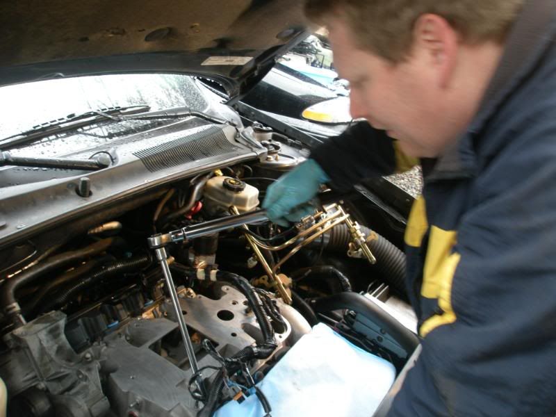
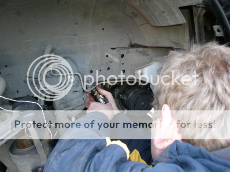
Remove 4 nuts, one stud and a vacuum line to remove the fuel rail. You can either tie it out of the way or remove it from the fuel lines. A special tool is required to remove the fuel lines.
The stud

Fuel lines requiring a fuel line removal tool:

Remove the supercharger ( There are several sensors and misc items that need to be disconnected). The throttlebody and BCS can stay on the SC.
Remove the alternator, ICM bracket and valve covers. I also found it helpful to remove the SC belt tensioner and idler bracket also. There is very little clearance, so you have to remove the rearward stud.

Remove the LIM by removing all 12 bolts. Take note of the coolant bypass fitting in the right side. They are plastic and are usually available in the help section at most part stores.
LIM to accessory bracket elbow

Remove the accessory belt tensioner bracket (3 bolts) above the water pump. There is another bypass fitting between this and the water pump. You will also need to remove the 2 bolts holding the heater core hoses on. The hose fitting will then slide out of the bracket. You can also remove the bolts in the front cover at this time. Leave the water pump attached, but remove the 4 bolts that go through the water pump to the block. There is one hidden bolt on the left side of the pump just below the outlet by the accessory bracket.
These are the heater core hoses in the accessory bracket

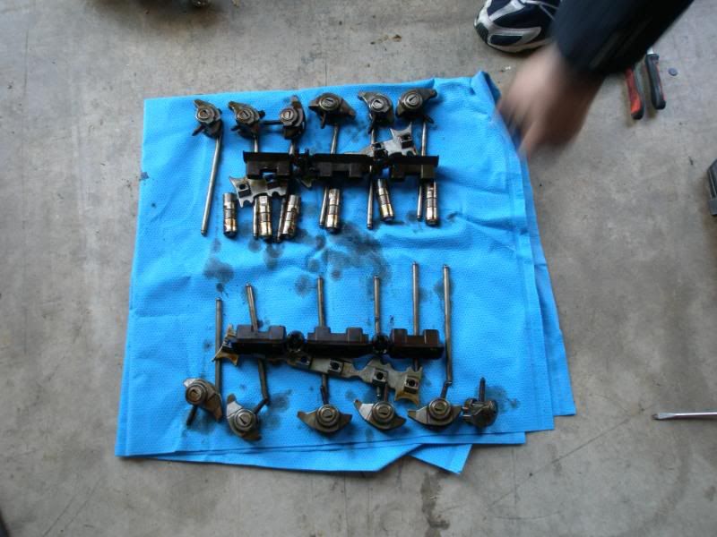
Remove the Rocker arms, push rods and lifters. You will want to keep them in the same position when reinstalling them in the engine. This includes which end of the pushrod goes to the lifter or rocker.
Remove the dust cover under the radiator.

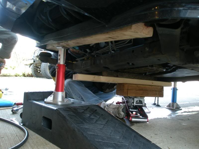
In the next step you will want to support the right front of the car so that the wheel can be removed and yet be able to lower the sub frame. You need to jack the car up high enough to remove the ramp from the right front. We found it best to use a 2 x 4 under the radiator support and put a jack stand towards the right end of it. We also put a 2 x 4 and jack stand under the uni-frame below the right front passenger door.
The red stand is under the radiator support and the blue one is under the frame with a 2 x 4 to spread the load
Placement of second stand (remember to put a 2 x 4 between to help spread the load)
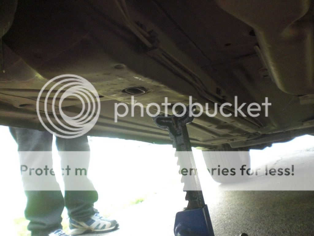
This is how it will look from the front

Remove the right front wheel and dust cover.
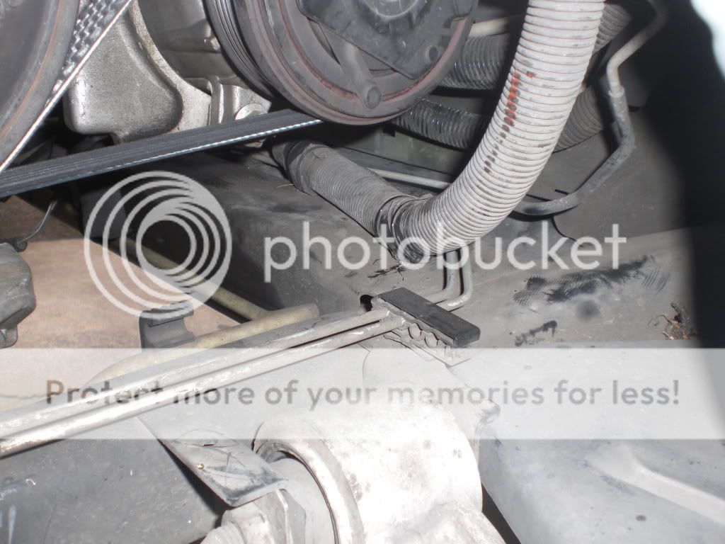
Next you will need a 2 x 4 between 32 and 36 inches and another piece 10 to 12 inches to support the motor and be able to lower the sub frame.
Place the longer 2 x 4 on the jack and center it front to rear on the right side of the sub frame and then place the shorter piece under the oil pan to support the motor.
Jack the 2 x 4’s up to make contact with the sub frame.
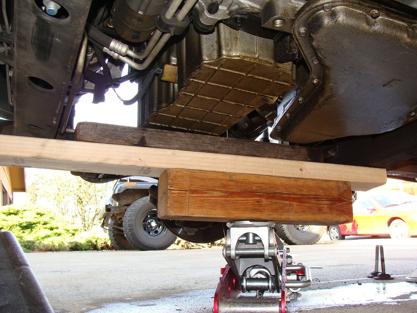
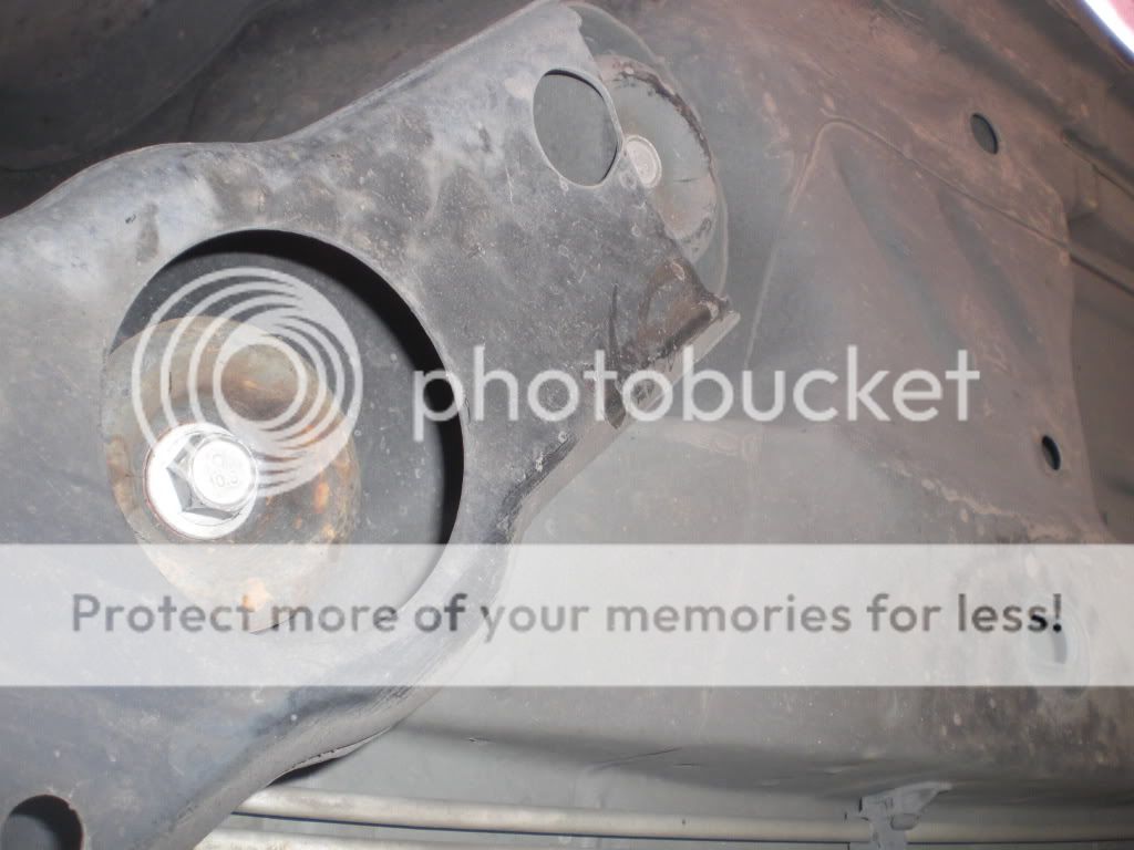
Remove the nut holding the motor mount bracket to the mount to lower the motor onto the 2 x 4 and jack. Once the tension is relieved and the jack has the weight of the motor, you can remove the 2 bolts holding the bracket to the oil pan. Place the bracket off to the side.


Remove the harmonic balancer and timing cover. Disconnect the cam sensor, crank sensor and oil pressure switch. You will need to remove 3 bolts from the oil pan that hold the front cover to oil pan seal. When removing the cover, you need to slide it off the front of the engine because it has 2 alignment pins. Be careful not to damage the oil pan seal.
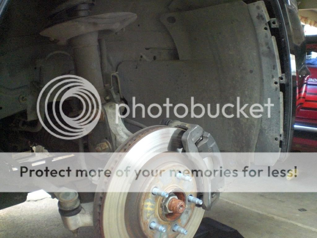
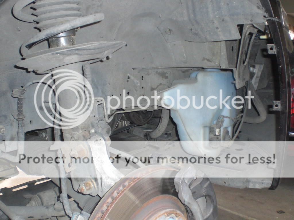
Remove bracket holding the brake line to the right front strut. remove caliber from bracket and hang with a piece of wire.
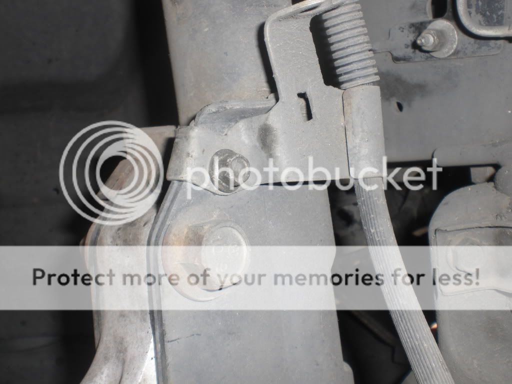
Remove the 3 bolts that hold the top mount of the strut.

Remove all 3 sub frame bolts on the right side and loosen all 3 on the left several turns. When you remove the ones on the right, you will see how long they are.

Slowly lower the jack supporting the motor and sub frame. You will need a minimum of 5.5 inches to get the cam to clear. While lowering, watch for anything that can get caught or pulled. I had to remove a harness clip on the right front corner of the sub frame.

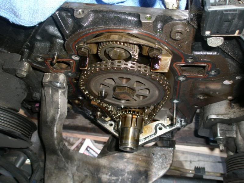
Once sub frame is lowered, you will need to break the cam sprocket bolt loose. After breaking it loose, set cylinder #1 to TDC and remove the timing set, cam thrust plate and balance shaft gear.
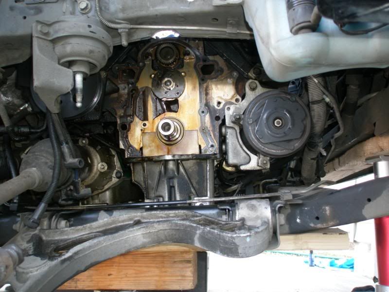
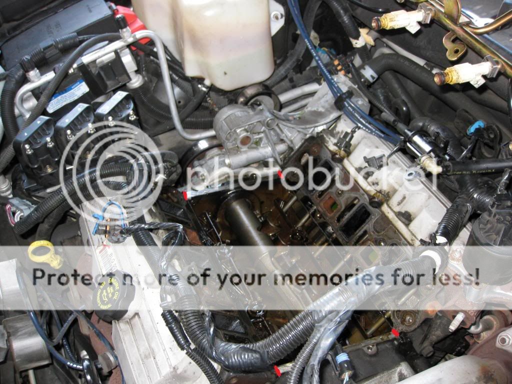
This is a picture with everything off except the thrust plate
Next you will need to put the cam sprocket back on and hand tighten the bolt. This will give you some leverage to balance the cam so you don't nick any of the bearings.
Now you are ready to gently slide the cam out.
Cam InstallRight now you should have the subframe lowered and the old cam out of the block
Prelube the new cam with the recommended engine prelube or what was provided with the cam. You will want to make sure to have all the lobes and cam journal lubricated all the way around. This is a lubrication to protect the cam until the motor gets the oil pumped up to it.
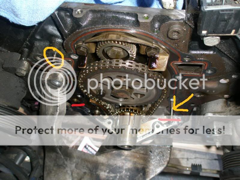
The red arrows indicate the bearing surfaces and the yellow are the lifter lobes. Be sure to coat them all the way around

To install the cam, you can either put a cam sprocket on or use a wooden dowel stuck in the end to help balance the weight. It is kind of tricky getting the cam to slide into all the bearings, so have patience. Be extremely careful not to ding any of the bearings and DO NOT force it in, it should slide in nice and smooth.
Installing the cam
Install the cam thrust plate in to keep the cam from sliding out and torque to 11 ft-lb.
At this point you can raise the subframe back up and torque the bolts to 140 ft-lb. DO NOT install the motor mount bracket. Leave the jack there to hold the motor until the front cover is installed.
Install the balance shaft gear and make sure to align timing marks.
Install the timing chain and gears. Be sure to put the woodruff key in the new cam. I had to thread the cam bolt in a couple of threads to pull out on the cam as the chain and gears were slid on because the cam wanted to slide into the block and not allow the key to align. Another one of those steps that requires patience. It is also recommended to replace the cam sprocket bolt and torque to 74 lb-ft and then 90 degrees.
Install the timing chain damper. Torque to 16 lb-ft.
Depending on what all is being replaced (oil pressure kit, oil pump, water pump, front seal) you need to prep the front cover for reinstallation. Clean off the old gaskets and clean the mating surfaces on the block and cover.
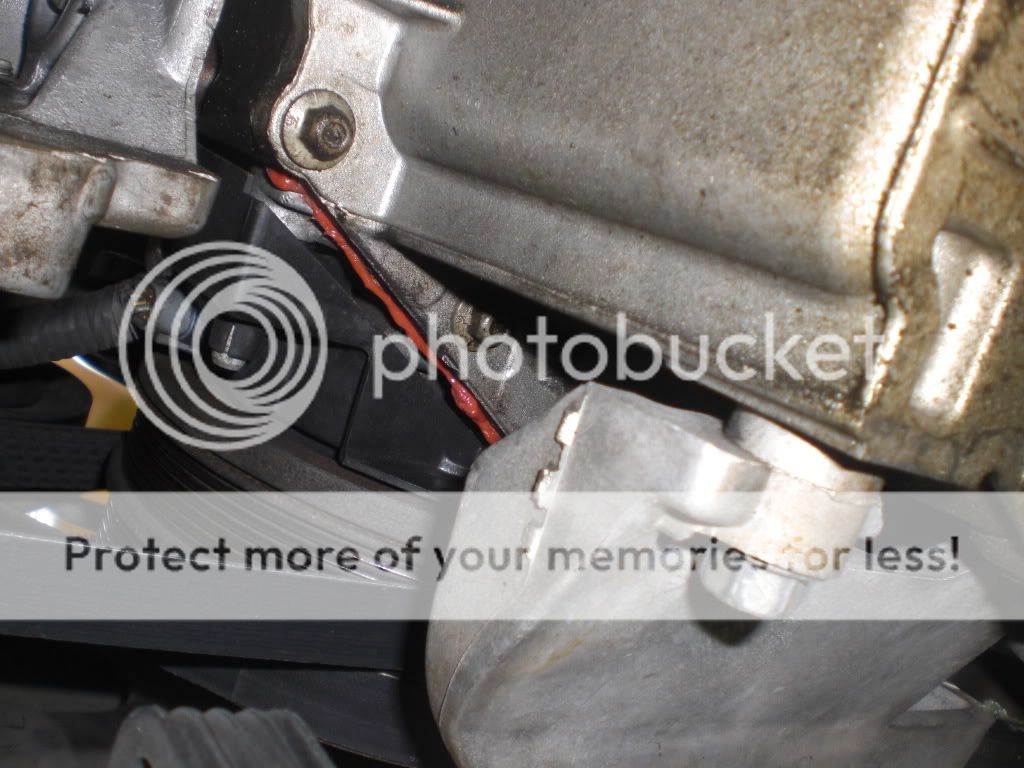
Prior to installing the front cover, you will need to put the gasket over the pins on the block and put sealant on the corners where the block, cover and oil pan meet. I also put a thin layer of sealant on the exposed oil pan gasket to make sure it doesn’t leak.
The yellow circle and arrow indicate the pins and the red indicates the place to apply the sealant
Install the front cover and torque to 15 ft-lb and then 40 degrees on the second pass. The oil pan bolts get 125 in-lb.
Put the motor mount bracket in place and thread the nut on several threads and then put the bolts in the oil pan. Once those are in, tighten up the nut and you should see the tension on the jack release. The mount bolts and nut get 35 lb-ft of torque.
Now the sensors can be reconnected and the harmonic balancer replaced (111 lb-ft first pass and then 76 degrees). The wiring harness connector on the subframe can also be reconnected.
At this point you can put the wheel liner back in and the right wheel on. It will also make it a little easier to remove the ramps by jacking each side up and pulling them out.
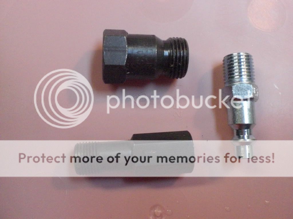
The next thing to do is to change out the springs. You will need a special fitting that will thread into the spark plug holes and thread an air fitting on the other end. Some have also done this by putting string into the cylinder to hold the valves up.
Airline fitting (we use the small one, but they are usually sold as a set)
***With the fitting threaded hand tight into the spark plug hole, attach the airline. You should see the motor try to turn over and bottom out the piston. You are basically filling the cylinder with air to hold the valve into the head while the spring is off.
Now you can remove the spring using a valve spring removal tool and a magnet to retreive the locks.
Valve spring compressor

Cmpresser tool being installed

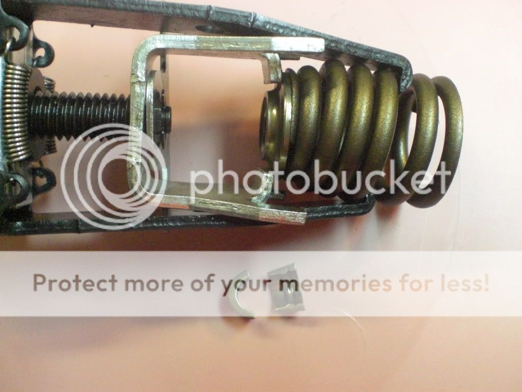
Spring, retainer and locks removed
Once the spring, locks and retainer are off, remove the spring and retainer from the tool. Put the new retainer on the new spring and compress it with the tool.
New spring and retainer (before compressed)

After compressed (ready to be slid over the valve stem)

Once compressed, slide it over the valve stem and seal and put the locks in place. It also helps to pull up on the tool while loosening it so the locks don’t fall out.
Repeat this for the other valve for that cylinder.When done with the second valve, proceed to the step below.
Remove airline first and then the fitting in the spark plug hole. Repeat from the *** above for each cylinder.
You are now ready to install the lifters, pushrods and rocker arms. It is recommended to change the rocker arm bolts.
The lifters will need to be prelubed on the outside diameters and then put a drop in the end the pushrod mates with.
Insert the lifters in each of the bores they were removed from. Take note of the orientation of the roller so it is aligned with the cam.
Once all the lifters are installed for one bank, install the lifter retainer (this keeps the roller lifters from spinning in the bores).
Once all the lifters are installed, insert each pushrod in it’s original lifter and orientation.
Use some pre-lube on the pivots of the rockers and the end where the pushrod makes contact. Remember the top of the engine will be dry, so don’t be afraid to lube things well in the assembly process.
Next, place the pedestal on one cylinder head and put the rockers on finger tight. Now you are ready to torque them. If you installed the reusable bolts (25 ft-lb), if you used the OEM bolts (11 ft-lb plus 90 degrees)
Once both banks of rockers are done, clean the gasket areas of the heads and block for the LIM and rocker covers.
I recommend using a cheap quart of oil to pour over the rockers and in the valley to flush any debris to the pan.
If not done yet, prepare the LIM, accessory belt tensioner bracket and other items for reinstallation. You can also do the supercharger oil and coupler at this time if desired.
Some like to install the accessory bracket after the LIM, but I chose to install it first. The choice is yours, it works either way.
Install the accessory belt tensioner bracket with the coolant elbow to the water pump. Torque to 37 ft-lb.
If desired, you can replace the o-rings on the heater core hoses before reinstalling them into the bracket. You can also put a bead of sealant around them also.
When ready to install the LIM, put sealant in the corner where the LIM, block and heads meet. Set the lim gaskets in place and then put more sealant in the same areas.
Put a bead of sealant around each o-ring on the other elbow that is between the accessory bracket and LIM. Insert into the bracket.
Install the LIM while watching the elbow so it slides into it. Torque thw LIM bolts to 11 ft-lb following the sequence in the FSM.
The next thing to install is the EGR valve to LIM tube. 21 ft-lb
Next you will need to place the gasket and o-rings on the LIM for the SC. Set the SC on the LIM and ensure a flat fit, you do not want any rocking. Install the bolts and torque to 17 ft-lb
The next thing to install will be the map sensor bracket on the back side of the SC. It is hard to get to once the fuel rail is installed.
Finally, the fuel rail goes on along with the ICM, alternator and any hoses or connections removed when starting.
Be sure to change the oil and install a filter before cranking the engine.
Fill the coolant and bleed the air if any is trapped.
Other than my photos, ther are also photos contained nere which were taken by WILLWREN and 2000SILVERBULLET.


